10
|
Installation | Broadband 3G™ Radar Installation Guide
Installation
Note: Follow these instructions carefully. Don’t take any shortcuts!
The broadband radar is factory sealed. It is not necessary to remove the cover. Removing the
cover will void the factory warranty.
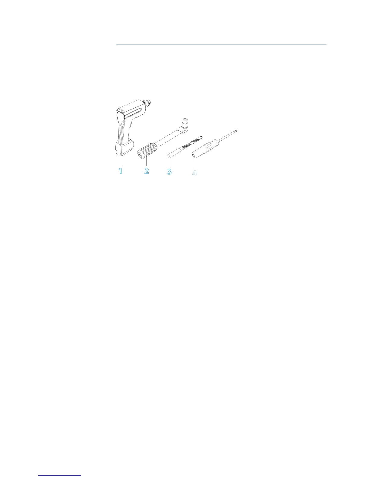
Tools Required
1
2
3
4
Choose the scanner location
The radar’s ability to detect targets greatly depends on the position of its scanner. The ideal
location for the scanner is high above the vessel’s keel line where there are no obstacles.
A higher installation position increases the radar ranging distance, but it also increases the
minimum range around the vessel where targets cannot be detected.
When you’re deciding on the location, consider the following:
The length of the interconnection cable supplied with your radar is usually suffi cient. If you
think you’ll need a longer cable, consult your dealer before installation. Optional cable lengths
are 10 m (33 ft), 20 m (65.5 ft) and 30 m (98 ft).
If you mount the scanner on a pedestal or base, ensure that rain and sea spray can drain away
rapidly, and the breather hole in the base can operate .
The scanner is usually installed parallel to the line of the keel.
DON’T DO THIS!
DON’T install the scanner too high up, which may cause degradation of the radar picture over
short ranges.
DON’T install the scanner close to lamps or exhaust outlets. The heat emissions may damage
the dome. Soot and smoke will degrade the performance of the radar.
DON’T install the scanner close to the antennas of other equipment such as direction fi nders,
VHF antennas, GPS equipment as it may cause interference.
DON’T install the scanner where a large obstruction (such as an exhaust stack) is at the same
level as the beam, because the obstruction is likely to generate false echoes and/or shadow
zones.
DON’T install the scanner where it will be subjected to strong vibrations because these vibra-
tions could degrade the performance of the radar.
DON’T install the scanner such that boat electronics with switch mode power supplies (such
as fi sh-fi nders and chart plotters) are in the beam of the antenna.
DON’T install the scanner directly on to a large fl at roof area. Use a pedestal to elevate the
scanner for radar beams to clear roof line (see “Considerations for direct roof mounting” on
page 11)
1. Drill
2. Torque wrench
3. Drill bit 9.5 mm (3/8”)
4. Screw driver
3