|
23
Setup and Con guration | Broadband 3G™ Radar Installation Guide
Adjust bearing alignment...
Adjust the heading marker. This is to align with the heading marker on the screen with the
center line of the vessel, this will compensate for any slight misalignment of the scanner dur-
ing installation. Any inaccuracy will be evident when using MARPA or chart overlay.
Point the boat to the end of a head land or peninsular. Adjust the bearing alignment so the
heading line touches the end of the same head land or peninsular.
Adjust local interference reject...
Interference from some onboard sources can interfere with the Broadband radar. One symp-
tom of this could be a large target on the screen that remains in the same relative bearing
even if the vessel changes direction. Choose from Local interference rejection LOW, MED or
HIGH. Default is LOW
Adjust antenna height...
Set the radar scanner height. The Radar uses this value to optimize sea clutter performance
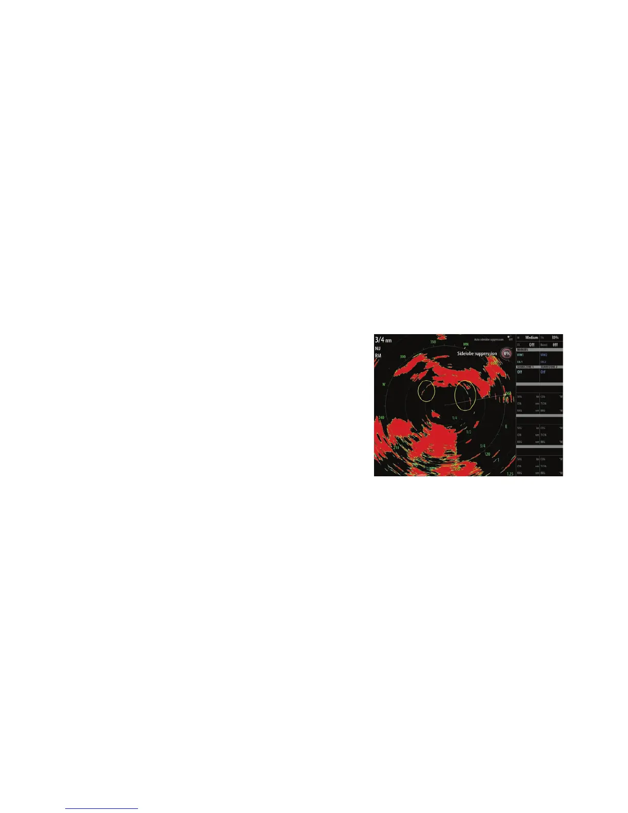
Sidelobe suppression...
Note: This control should only be adjusted by experienced radar users. Target loss in harbour
environments may occur if this control is not adjusted correctly.
Occasionally false target returns can occur
adjacent to strong target returns such as
large ships or container ports. This occurs
because not all of the transmitted radar
energy can be focused into a single beam
by the radar antenna, a small amount en-
ergy is transmitted in other directions. This
energy is referred to as sidelobe energy
and occurs in all radar systems. The returns
caused by sidelobes tend to appear as arcs:
When the radar is mounted where there are metallic objects near the radar, sidelobe energy
increases because the beam focus is degraded. The increased sidelobe returns can be elimi-
nated using the Sidelobe Suppression control in the Radar installation menu.
By default this control is set to Auto and normally should not need to be adjusted. However
if there is signifi cant metallic clutter around the radar, sidelobe suppression may need to be
increased. The control should be adjusted as follows:
1. Set Radar range to between 1/2nm to 1nm and Sidelobe Suppression to Auto.
2. Take the vessel to a location where sidelobe returns are likely to be seen. Typically this would
be near a large ship, container port, or metal bridge
3. Traverse the area until the strongest sidelobe returns are seen.
4. Change Auto sidelobe suppression to OFF then select and adjust the sidelobe suppression
control until the sidelobe returns are just eliminated. You may need to monitor 5-10 radar
sweeps to be sure they have been eliminated.
5. Traverse the area again and readjust if sidelobes returns still occur.
6. Exit the installation menu.