14
|
Installation | Broadband 3G™ Radar Installation Guide
Connect interconnection cable to the scanner
The scanner interconnection cable connects the scanner to the RI10 interface box (or
Lowrance HDS via and ethernet adapter cable -U.S only). The cable connects to the scanner
using a 14 pin connector.
Protect the connectors when pulling cable through the boat and avoid putting strain on to
the connectors.
The interconnection cable is 9 mm in diameter. A 14 mm hole will be required in order for the
RJ45 connector to pass through (Interface box end) or 24 mm for the scanner end connector.
Run the interconnection cable between the scanner and the location of the radar interface
box.
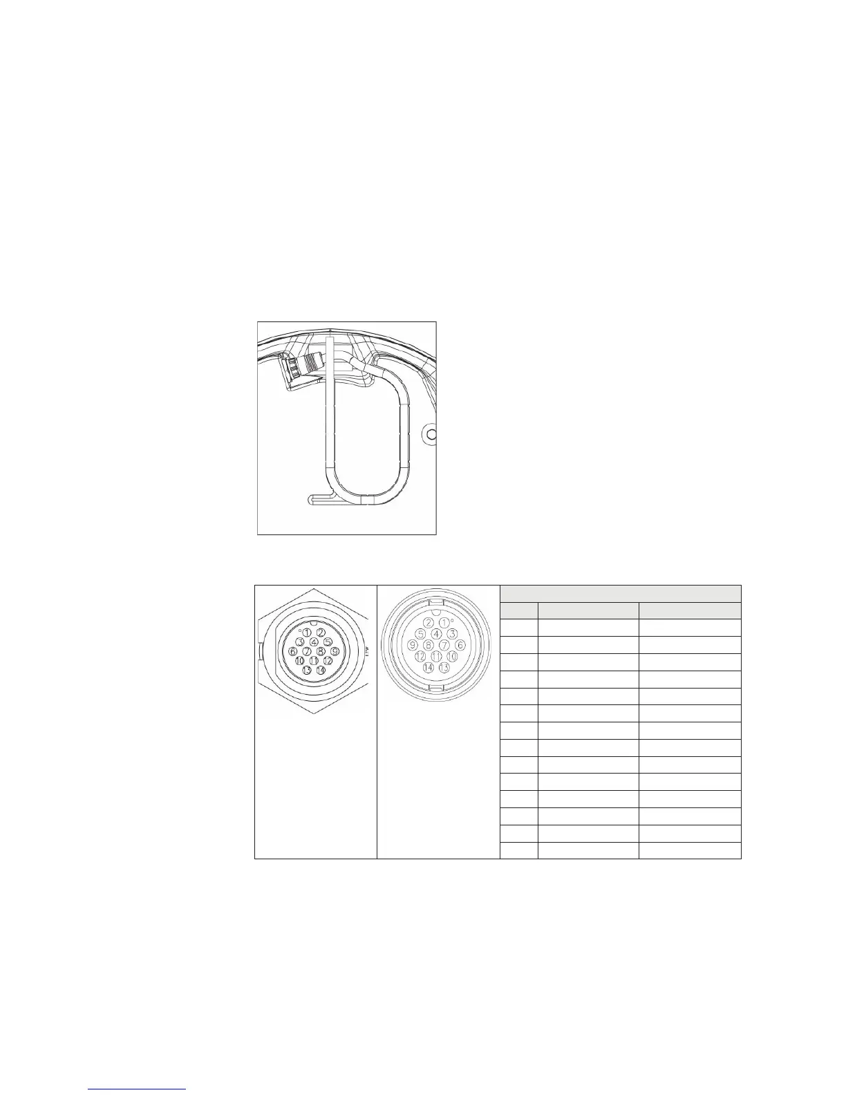
Insert cable connector on to the male 14 pin plug on the scanner.
Take care to align the connector correctly to avoid bending the pins. Secure the locking collar
by rotating clockwise until it clicks.
Feed and secure the cable into the cable retention channel.
Scanner Interconnection cable pin out
Scanner connector
Cable connector
Diameter = 23 mm
Pin-out
Conn Wire color RJ45
1 Black Tinned wire
2 Red Tinned wire
3 Yellow Tinned wire
4 Drain Tinned wire
5 N/A N/A
6 Blue RJ45 Pin 4
7 White / Blue RJ45 Pin 5
8 White / Brown RJ45 Pin 7
9 Brown RJ45 Pin 8
10 White / Green RJ45 Pin 3
11 N/A N/A
12 White / Orange RJ45 Pin 1
13 Green RJ45 Pin 6
14 Orange RJ45 Pin 2