|
15
Installation | Broadband 3G™ Radar Installation Guide
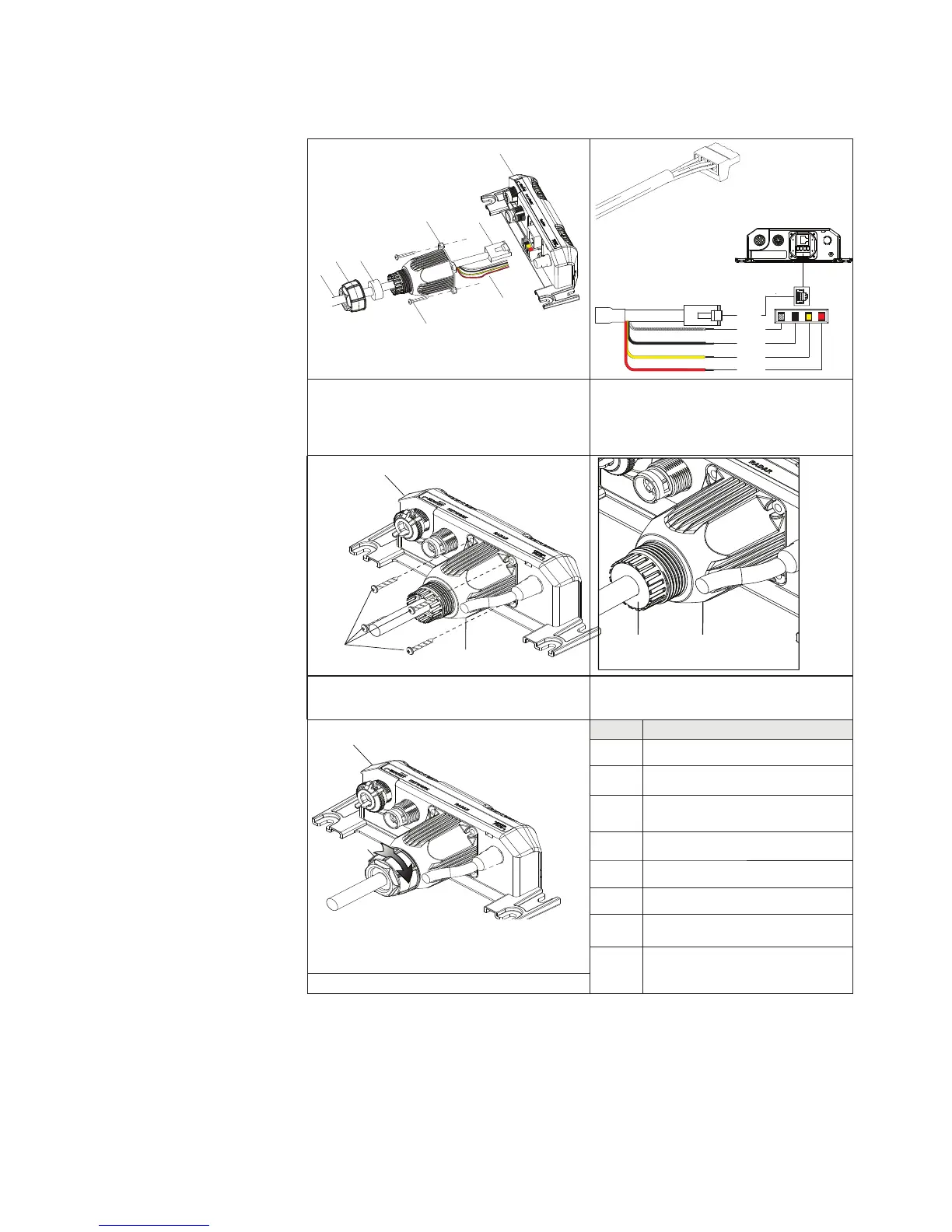
Connect the interconnection cable to radar interface box
To connect interconnection cable to Lowrance HDS (USA only) (see “Lowrance HDS USA” on
page 17)
A
B
D
E
C
F
G
Data
Red
Yellow
Black
Shield
1. Slide (F), (E) and (D) over the RJ45 and data
wires of the scanner interconnection cable (G).
2. Connect data wires to the phoenix con-
nector.
3. Connect RJ45 and phoenix connector to
the radar interface box.
H
D
A
E
D
4. Secure (D) to the radar interface box using
the four supplied screws (H).
5. Slide (E) along the cable (G) and press
into the cable gland housing (D).
F
A
Key Description
A Radar interface box
B Radar data connector RJ45
C Power wires (see “Connect power”
on page 21)
D Cable gland housing
E Gland washer
F Lock nut
G scanner interconnection cable
H Screws x 4 M3x12 mm Phillips pan
head
6. Rotate (F) clockwise to secure.
To remove the scanner interconnection cable, follow the above procedure in reverse order.
To avoid damaging the connectors when removing the scanner interconnection cable, it is
important to remove the cable gland washer before trying to remove the cable gland hous-
ing.