| 11
Installation and wiring | BSM-3 Installation Manual
Wiring
The BSM-3 has convenient connectors to attach power and
transducers. It is also supplied with cable glands to allow for
transducers that don’t have a 7 pin connector.
The BSM-3 contains high voltages and specialized parts; the
operator should never remove the module’s cover without
removing the power connection.
Removing the transducer cable from the BSM-3 while the
module is powered on can cause sparks. Remove the transducer
cables only after the module has been disconnected from its
power source.
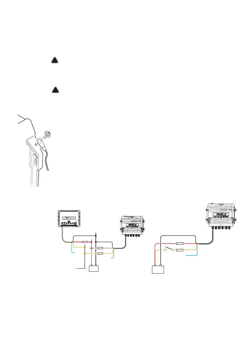
Grounding the unit
For additional safety install grounding cable in ground screw hole as
indicated on illustration. Recommended 16 awg wire.
Power
The unit has no power key and will turn on when power is applied.
When used in an NSE/NSS/NSO evo2 system, it is recommended to
connect the BSM-3 to the Power control bus, and set display system
to power control master.
BSM-2
12 - 24 V DC
Red
Black
Yellow
Red
Black
Yellow
+
_
NSE
Power
Control bus
Blue
(n/c)
Blue
(n/c)
BSM-2
Switch
12 - 24 V DC
+
_
Red
Black
Yellow
Blue
(n/c)
If the BSM-3 is connected directly to the vessel’s battery, the module
will continue to draw power even when it is not in operation. It is
recommended that the yellow power cable wire be fitted with an
optional on/off switch, allowing the BSM-3 to be powered off when
not in use.