Installation
20222303 / A 11
3 INSTALLATION
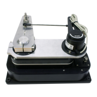
3.1 Mechanical mounting
The direct drive drives the rudder via a draglink to the existing
tiller lever or quadrant or via a separate tiller lever. The length of
the draglink and a separate tiller lever (if necessary) have to be
specified when ordering. See the Direct Drive Specification
Form (page 23) for available draglink lengths and tiller levers.
The draglink part numbers are listed on page 22.
The drive can be mounted behind or next to the rudderstock,
driving the rudder directly or in front of the pedestal driving the
rudder via the pedestal.
The direct drive com
es as standard with a 16 mm pin 165 mm from
the center of the output lever. The pin can be moved to the 130 mm
position from the center, but must be secured with Loctite.
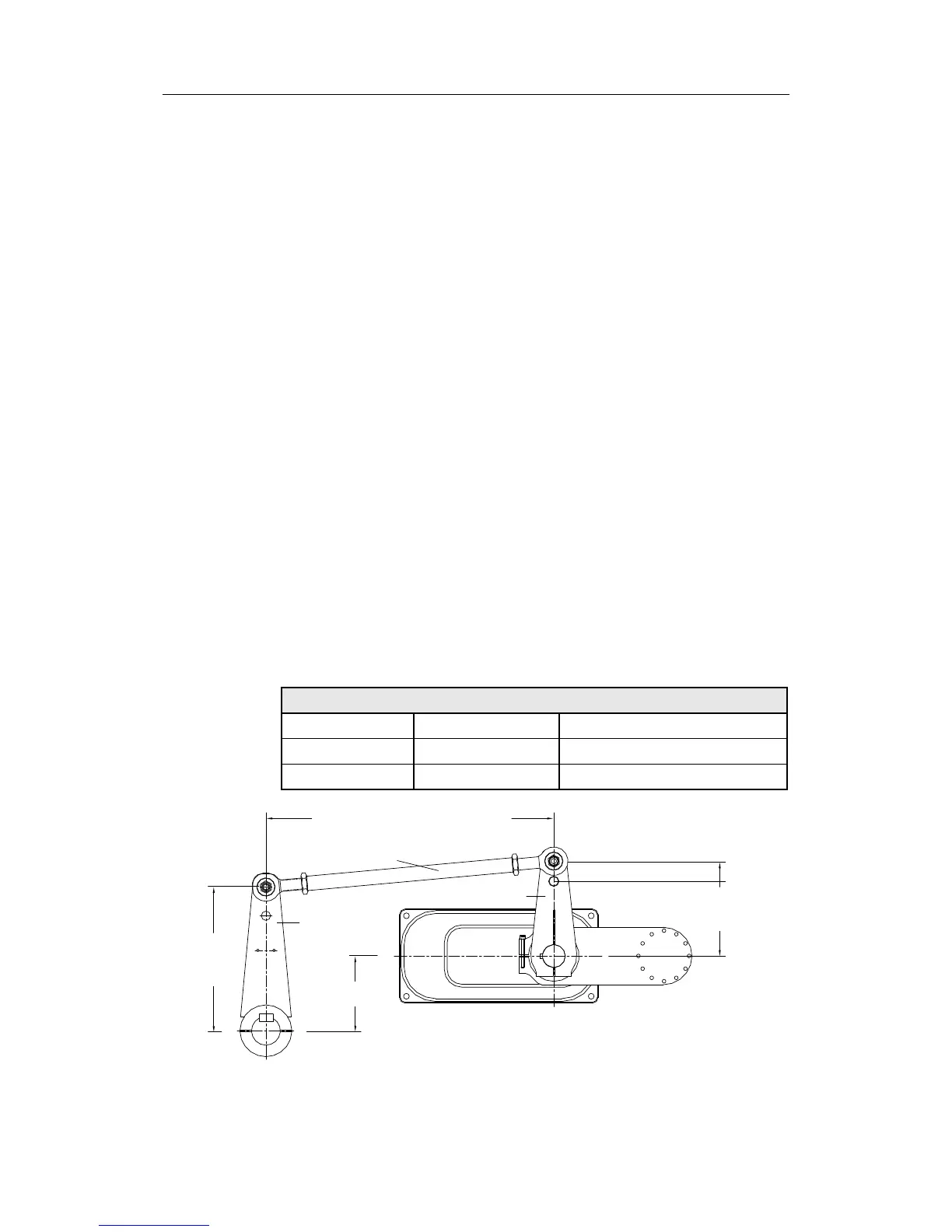
The direct drive uses “wide angle geometry”. The result of this is
a 130° travel of the output lever and a 72° travel of the tiller
lever( see Figure 3-2). To achieve an equal travel of the drive at
port and starboard, the center point of the output lever needs an
offset to the rudderstock centre. The offset depends on the used
lever centers. Following table shows the correct offset distances:
Operating centers in mm valid for 72° (2x36°) rudder travel.
Output center Offset distance Tiller center
130 106 200
165 127 250
Offset
Tiller
center
Output
center
Min. 300 - max 2000 mm
165 mm
130 mm
Output lever
Tiller lever
Draglink
Figure 3-1 Mechanical mounting