PAGE | 10
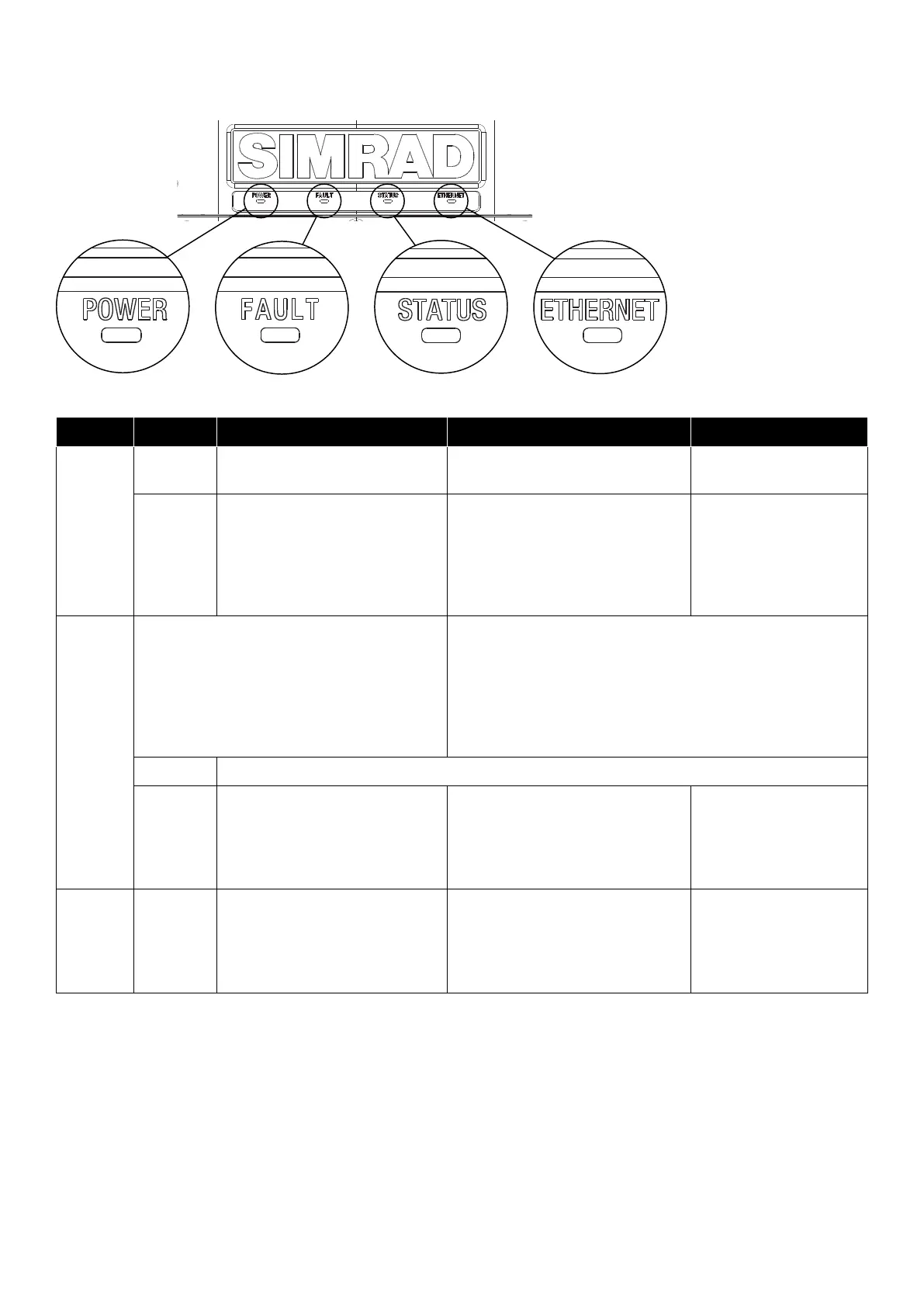
RI-50 LED indicator lights
LED lights on the front of the RI-50 communicate its operating status.
LED Color Indication Possible cause Action
Power Green
steady
Power is applied Normal operation Not applicable
OFF No supply voltage Supply voltage (24 V DC) missing • Ensure 12-24 V
switch is in 24 V
position.
• Ensure remote
switch is set to ON.
• Replace the RI-50.
Fault The fault indicator shows existing conditions
as steady colors and historic conditions as
ashing patterns.
Re-power the RI-50 to clear a fault/warning
indication.
Faults are dened as conditions that could cause damage to
the equipment.
Warnings indicate conditions that can cause the RI-50 to
change the operating state of the radar e.g., switching it to
standby.
The historic indication helps to identify the cause of
intermittent problems.
OFF Normal operation
Blue Under or over voltage Supply voltage to the RI-50
outside of supply limits 20 V DC to
31.2 V DC
• Check supply voltage
• Check DC supply
cables, connections,
and proper AWG for
cable length.
Fault Purple Over current including short
circuits
Input current > 20 A or output
current > 8 A
• Check the output
cable.
• Check the radar
pedestal
• Replace the RI-50.