PAGE | 23
Procedure
1 On the electric switchboard, switch OFF the radar main breaker, and attach a card stating:
“WORK IN PROGRESS - DO NOT SWITCH ON”.
2 On the R5000 PSU, switch the power switch to the OFF position, and attach a card stating:
“WORK IN PROGRESS - DO NOT SWITCH ON”.
3 Switch safety switch to the OFF position.
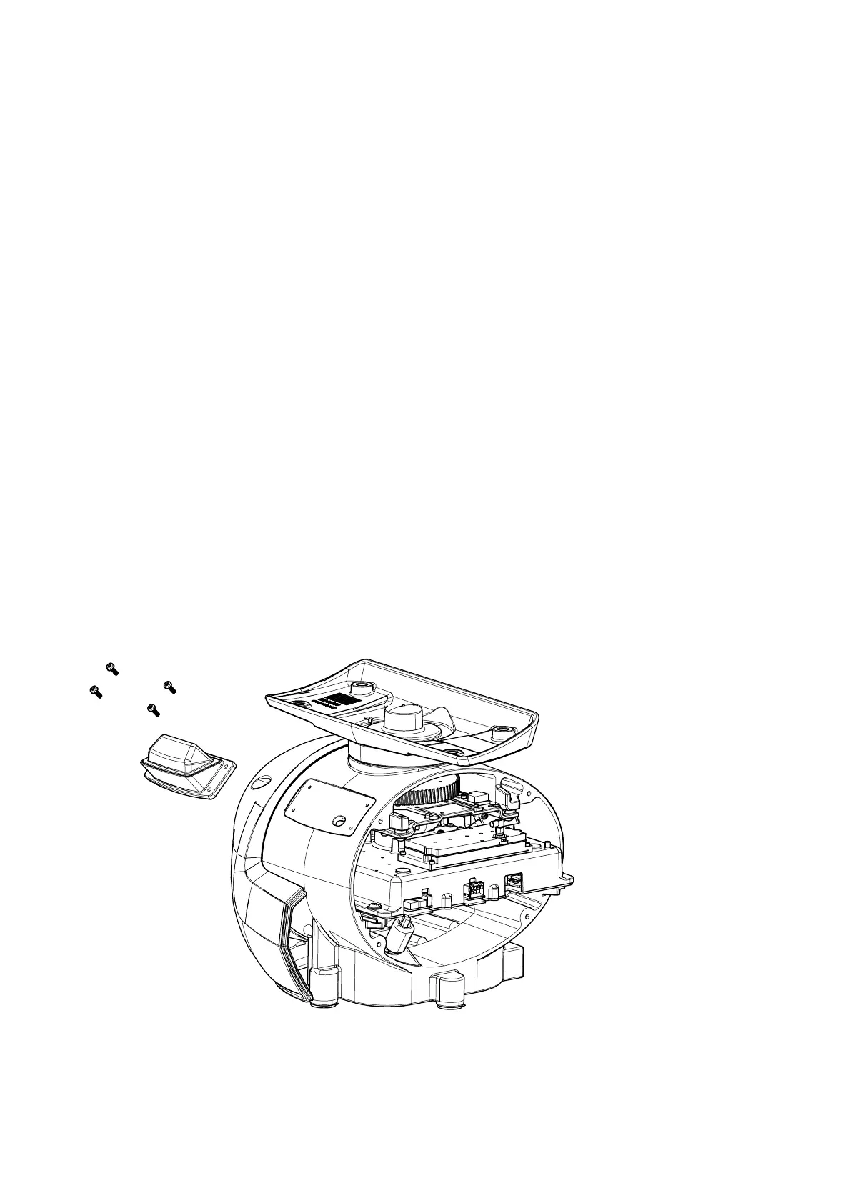
4 Use the 5 mm Allen
®
key to loosen the four captive screws to open the port end cap.
5 With the 8 mm open wrench, loosen and remove the SMA connector on the performance monitor module.
6 Remove the 2 screws (B) with a 90° 2.5 mm Allen
®
key.
7 Loosen the 2 internal screws (C) with a 90° 2.5 mm Allen
®
key.
8 Slide out performance monitor module.
9 Disconnect digital cable from the transceiver module.
Install new performance monitor module installation
10 Connect digital cable to the transceiver module.
11 Slide new performance monitor module into the pedestal
12 Insert 2 screws (B) and tighten with 90° 2.5 mm Allen
®
key
13 Tighten 2 internal screws (C) with 90° 2.5 mm Allen
®
key
14 Reconnect the SMA connector on the performance monitor module, and tighten with 8 mm open wrench.
15 Check that O-ring is correctly seated in the end cap before closing the pedestal.
16 Use the 5 mm Allen
®
key to tighten the four captive screws in the endcap.
17 Switch the safety switch to the ON position.
18 On the electric switchboard, set the radar main breaker to ON and remove the card reading:
“WORK IN PROGRESS - DO NOT SWITCH ON”.
19 On the R5000 PSU, switch the power switch to the ON position and remove the card reading:
“WORK IN PROGRESS - DO NOT SWITCH ON”.
20 The radar is ready to be tested.
Performance monitor antenna replacement
Tools needed
• Performance monitor antenna spare kit 000-16091-001
• 8 mm open wrench
• 5 mm Allen
®
key
• T20 Torx
®
key