22 |
Wiring |Halo pulse compression radar installation manual
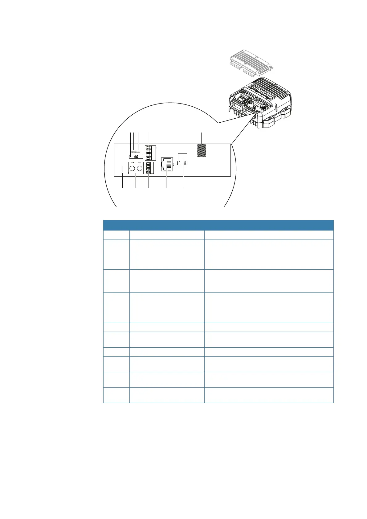
RI-12 connections
6 7
12 3
8 9 10
4 5
No. Name Description
1
FUSE 25 Amp blade fuse
2
Power control: REMOTE Remote power control activation jumper. Move to
REMOTE position so radar power state is controlled
by a multifunction display or switch (see “Remote
power control” on page 27)
3
Power control: AUTO Radar will turn on when power is applied to the
main power connector. Remote power wire on AUX
IN port is ignored
4
SCANNER POWER Large green connector: Provides 36 V DC up to the
pedestal and power for the park brake. Connect the
four wires of the interconnection cable matching
the color coded sticker on the connector
5
NMEA 2000 Micro-C: NMEA 2000 network connection
6
SCREEN Alternative chassis ground connection (see
“Grounding requirements” on page 26)
7
- SUPPLY+ 12 or 24 V DC input
8
AUX IN Small connector: NMEA 0183 data input, remote
power on and DC input for the antenna park brake
9
SCANNER RJ45: Ethernet data from the pedestal. Connect the
RJ45 connector of the interconnection cable
10 NETWORK/MFD RJ45: Connects the radar to the navigation Ethernet
network