Ethernet connector
The unit is equipped with an Ethernet port, which allows connecting the unit to your
network using the 5 pin Ethernet connector.
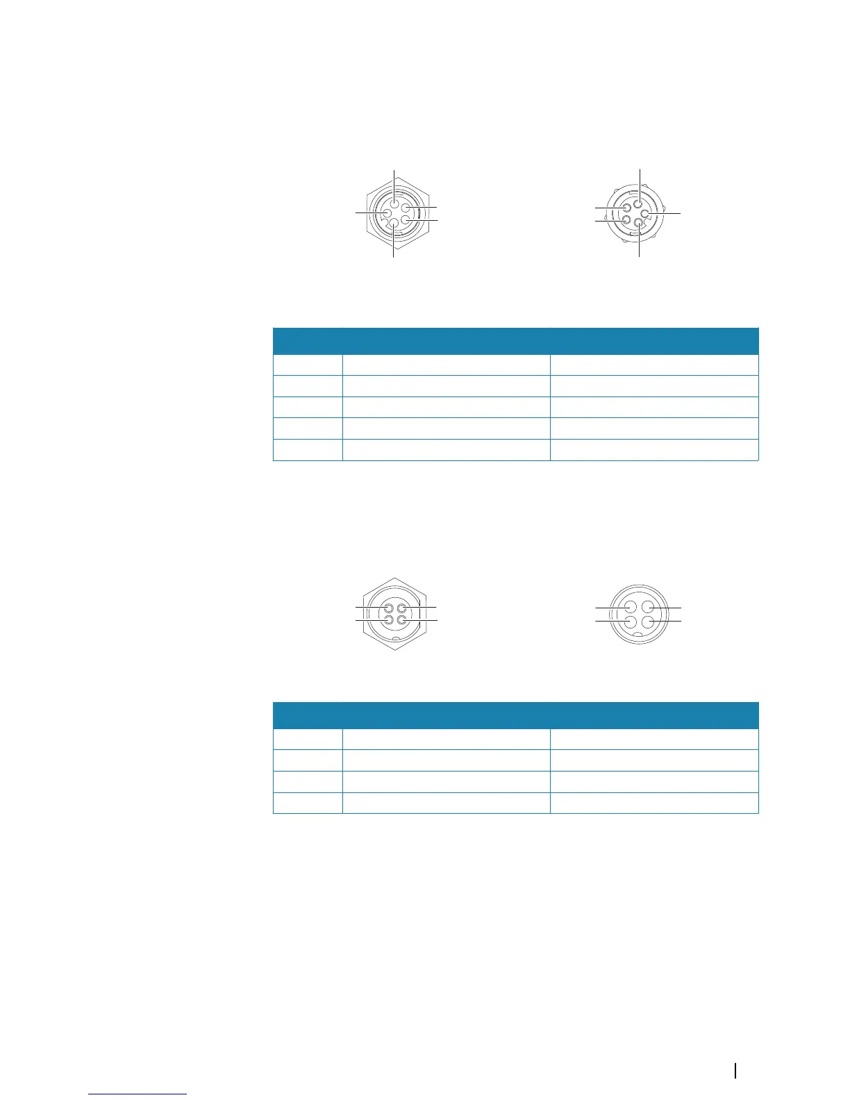
Cable plug (male)
Key Purpose Color
1 Transmit positive TX+ Blue/White
2 Transmit negative TX- Blue
3 Receive positive RX+ Orange/White
4 Receive negative RX- Orange
5 Shield Bare
Power connection
The unit is designed to be powered by a 12 or 24 VDC system. It is protected against reverse
polarity, under voltage and over voltage (for a limited duration). A fuse should be fitted to the
positive supply; 2 A for the 9" model and 5 A for the 16" model.
Cable plug (female)
Key Purpose Color
1 -12/24 VDC Black
2 External alarm Blue
3 Power control Yellow
4 +12/24 VDC Red
Power Control connection
The yellow Power Control wire in the power cable is an input that will turn on the unit when
power is applied.
Power Control unconnected
Device will turn on and off when the power button on the front of the unit is pressed. Leave
the yellow Power Control wire disconnected and tape or heat-shrink the end to prevent
shorting.
Power Control to supply positive (auto on)
Device will turn on immediately when power is applied. Common the yellow wire with the
red wire after the fuse.
Installation | S2009-2016 Fish Finder User Manual
29