1.6.2 Release six 1/4-in pan head screws securing the keyboard backing plate to the upper case. This allows the plate, with membrane attached,
to be lifted clear revealing the keyboard bubble mat below. The membrane is separated from the plate by carefully breaking the adhesive seal
holding the ribbon cables in position; the bubble mat is simply lifted from its position revealing a set of keys below.
1.6.3 Individual keys can be removed for cleaning by holding the key depressed and gently prising the retaining sleeve off the underside of the key
using a small screwdriver inserted under the rim.
2. ASSEMBLY
2.1 Assembly of the QL and its component parts is generally the reverse of disassembly. Points worthy of note are given below.
2.2 Loudspeaker. Attach double-sided adhesive tape, locate base over locating dowels adjacent to grille in the lower case and apply pressure to
effect an even bond.
2.3 Circuit Board. Locate RESET button end first and once secured, replace the microdrive extension bung and loudspeaker leads. Replace reset
button.
2.4 Microdrives. The ULA on the microdrive fitted in the left-hand (MDV1) position is protected by an RF shield. Ensure that the shield is in place
before starting re-assembly. Start assembly by straightening the bare wire-ends of the ribbon cables and then pushing them hone in their
respective sockets. Care is required to ensure the connections are made satisfactorily.
2.5 Keyboard. The bubble mat, membrane and backing plate are perforated to accommodate six locating dowels moulded in the upper case. It
may prove advantageous to release the adhesive bond between the membrane and the backing plate to aid alignment.
2.6 Case Assembly. Before screwing the case halves together, reconnect the keyboard ribbon cables and LEDs to their sockets on the circuit
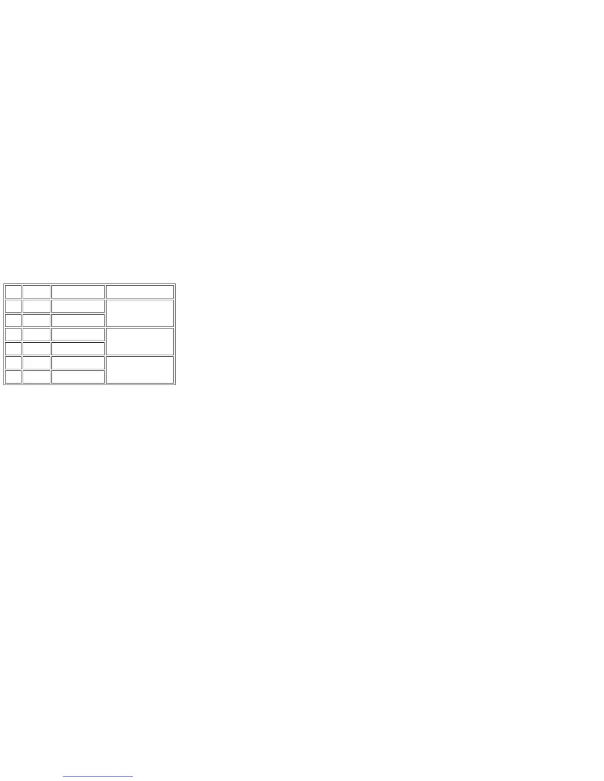
board. The LED connections are as follows:
Pin Diode Wire Colour Function
1 D21k Black
MDV2 (red)
2 D21a Grey
3 D20k Black
MDV1 (red)
4 D20a White
5 D27k Black
POWER (yellow)
6 D27a Red