2. PARTS LISTS / MODIFICATION HISTORY
2.1 Parts lists for the Sinclair QL are presented in tabular form. They cover p.c. board Issue 5 (build standard D6 to D13) and p.c. board Issue 6
(build standard 14 and beyond). The Issue 6 p.c. board introduces a number of relatively minor circuit changes from Issue 5. These are illustrated in
Figures 5.1 and 5.2 and itemised in Tables 5.1 to 5.5 under separate columns labelled Issue 5 and Issue 6.
2.2 Items listed on Issue 5 relate to build standard D13, incorporating the latest version firmware (i.e. 32k and 16k JM masked ROMs in IC33, IC34
respectively). Earlier build standards (D6 to D10) saw the progressive introduction of improved firmware starting with a pickaback 16k EPROM
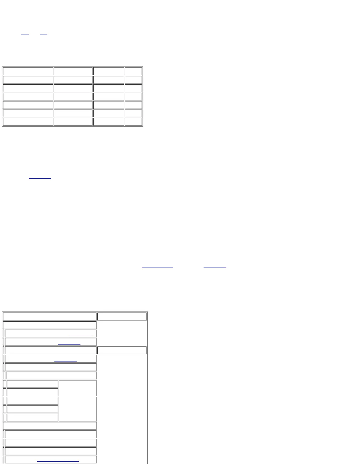
replacing the external 'dongle'. A history of these early units is tabulated below.
BUILD STANDARD IC33 IC34 MASK
D6 2 x 16k EPROM 16k EPROM AH
D7 2 x 16k EPROM 16k EPROM JM
D8 32k ROM 16k EPROM AH
D9 32k ROM 16k ROM AH
D10 32k EPROM 16k EPROM JM
D11-D14 32k ROM 16k ROM JM
2.3 Build standard D12 saw the introduction of modifications to the microdrive circuits foil owed by a new microdrive cartridge chassis at build
standard D13. The JM version ROM firmware and microdrive improvements were carried out to Issue 6 (build standards D14, D15).
3. RETROSPECTIVE (MANDATORY) MODIFICATIONS
3.1 In order to improve performance and reliability the following components must be added/replaced on all pre-build standard 12 QLs returned for
repair (see Section 4).
1. R104 (82 Ω) introduced in TR1 collector circuit.
2. R92 (formerly 220 Ω) increased to 390 Ω.
3. R105/R106 (1 kΩ) introduced across C19, D17.
4. D22/D23 (1N4148) introduced in series with R100/R101.
5. R102/R103 (33 kΩ) introduced between IC23 pins 21 and 19 and VM12 (-12 V rail).
6. firmware (IC33, IC34) to be upgraded to build standard D11.
4. NOTES TO TABLES
1. Early Issue 5 boards fitted with 43 kΩ resistors; do not replace unless it does not meet colour test criteria.
2. Retrospective (mandatory) modification required - see sub-section 3 (above) and Section 4 - Fault Diagnosis and Repair.
3. Fitted according to build standard and Issue.
4. BC183P is alternative type - NOTE: leads are reverse of BC184.
5. IC17 only fitted on Issue 5 EPROM versions.
6. IC38 replaces IC27 on Issue 6 versions.
TABLE 5.1 GENERAL ASSEMBLY
Description Manufacturer/Type
QL Base Assembly
Microdrive Chassis (2 off) - Table 5.3
Final PCB Assembly - Table 5.5
Loudspeaker Assembly 60 Ω, 23 mm, TV
Heatsink Assembly - Table 5.2
Bottom Case Moulding
Bottom Case Fixings
1/4-in self-tap (2 off)
PCB Fixings
Fibre washer (2 off)
5/16-in self-tap (2 off)
MDV Fixings1/2-in self-tap (2 off)
3/4-in self-tap (2 off)
QL Keyboard Assembly
Yellow LED (D27)
Red LED - 2 off (D20, D21)
QL Membrane
Keyboard Backplate