SECTION 3
SYSTEM TEST
1. Introduction
2. System Test
3. Procedure
1. Power-Up
2. Colour Test
3. Sound Test
4. Network Test
5. RS232C Loopback Test
6. Keyboard Test
7. Joystick Test
8. Real-Time Clock Test
9. Microdrive 2 Test
10. Microdrive 1 Test
11. Microdrive Tape Not Inserted Correctly
12. End of Test
1. INTRODUCTION
1.1 The use of the following test procedure is strongly recommended after carrying out unit repairs, thus ensuring that a once defective unit is
completely operational before return to the owner. The procedures can also be used effectively during fault diagnosis (Section 4).
1.2 Adjustments. The pre-Issue 6 QLs have a trimming capacitor TCI associated with the real time clock. It is factory-set to give a clock frequency
of 32.768 kHz at IC23 pins 30 and 31 and should not require further adjustment.
2. SYSTEM TEST
2.1 The system test is conducted with the QL connected to a colour monitor and a domestic colour TV receiver so checking both display paths.
Additional test equipment is required as follows:
1. System 2 Test Software - supplied as microdrive cartridge.
2. 2-off blank microdrive cartridges - passed as being suitable for system test.
3. RS232C loopback cable
4. 2-off industry standard joysticks
2.2 With the QL powered-up and the test software loaded and running, the test progresses through 9 well-defined states during which each of the
QL's functions is exercised. Some stages require the operator to respond to prompts displayed on the TV/monitor, others run autonomously
outputting only a test 'passed' or 'failed' message. At the end of system test the message QL TEST COMPLETE is displayed.
3. PROCEDURE
3.1 Power Up
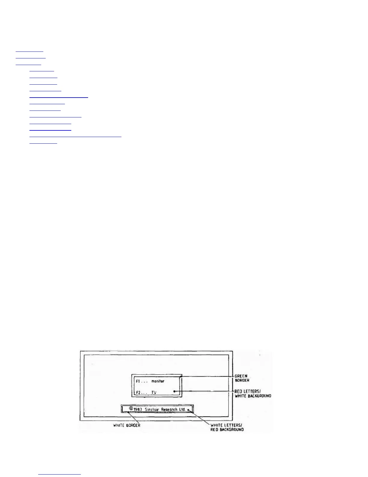
3.1.1 Connect the QL and power-up as if for normal use; check that the yellow 'power on' LED is illuminated and the following message is
displayed on both screens:
3.1.2 Connect the RS232 loopback cable, connect the joysticks to the QL's CTL1 and CTL2 sockets, insert the system 2 test cartridge in
microdrive 1 (MDV1) and press the F2 key. Check that the microdrive 1 LED lights up when the drive is running.
3.1.3 At some stage during program loading a title page is displayed briefly. A short time later two bleeps are heard and a message is displayed
requesting a blank cartridge to be placed in MDV2.