APPENDIX C TO SECTION 4
MANDATORY MODIFICATIONS
1. Fitment Checks
2. Improvement to Microdrive Performance
1. FITMENT CHECKS
1.1 Refer to the mandatory modifications described on page 4.3 and page 5.1 in this manual. To check that if these modifications have been
made, look for R102 and R103 through the SER1 port. If these resistors are in place you can assume that the other modifications have been
carried out. With build state D12 or higher the modifications have already been incorporated.
2. IMPROVEMENT TO MICRODRIVE PERFORMANCE
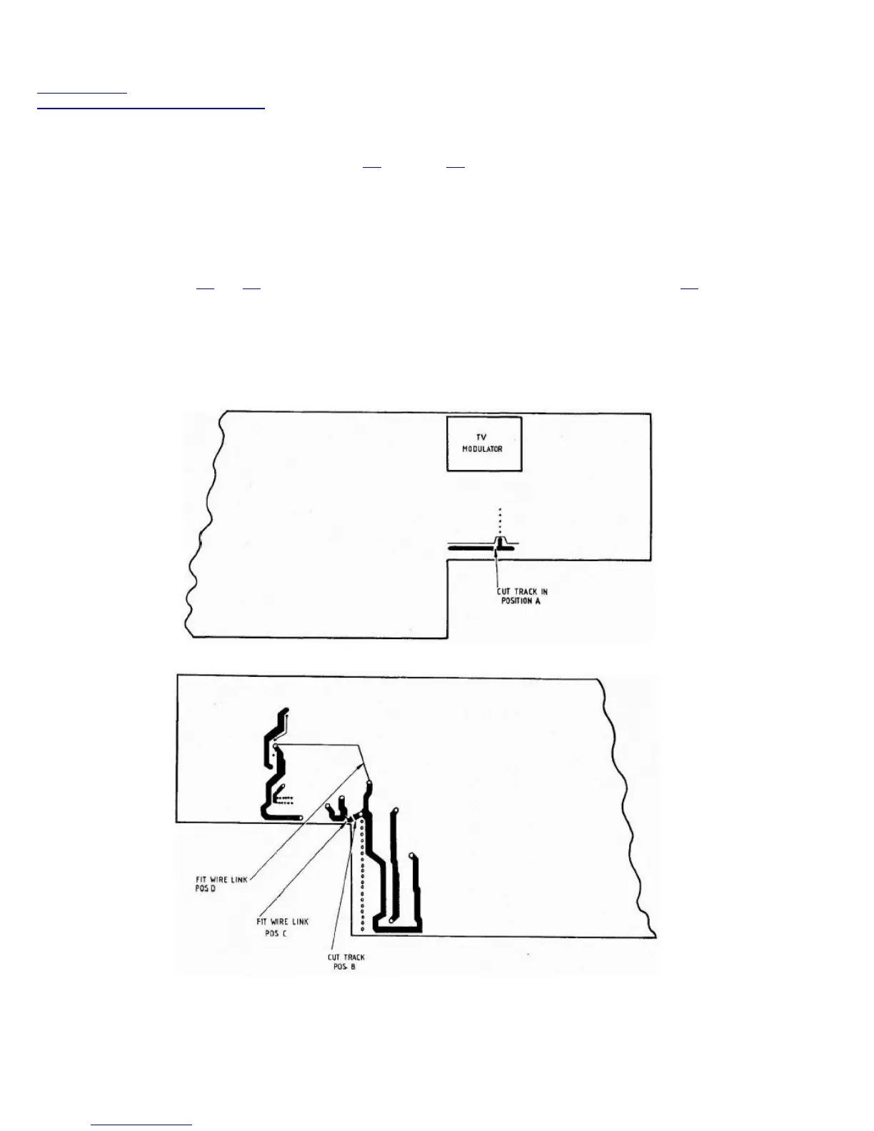
2.1 On any QL requiring repair, it is recommended that the following modification be automatically carried out at the same time. On Issue 5 boards,
cut the +5V track in position A on the component side of the board and in position B on the solder side. Then connect two links as shown in
positions C and D. (See Figures C1 and C2). On Issue 6 boards, both track cuts are on the solder side. (See Figure C3). All current production
incorporates this modification, which is identified by serial number D16 or higher, or modification label A4 or higher.
3. COLLAR FOR QL MICRODRIVE 2
3.1 On any QL for repair, fit a special collar beneath the far right fixing screw of MDV2 (the screw by the side spring). This is to prevent the lid of the
QL from hitting the top of the MDV2 board, which can upset the position of the head. Use a countersunk screw in place of the original one. Collars
are available from Sinclair's normal spares distribution channels.
FIGURE C1 ISSUE 5 BOARD - COMPONENT SIDE (SRL/EI/1118-1)
FIGURE C2 ISSUE 5 BOARD - SOLDER SIDE (SRL/EI/1118-2)