SECTION 4
FAULT DIAGNOSIS AND REPAIR
1. Introduction
1. Test Equipment
2. Modification History
3. Mandatory Modifications
2. Fault Diagnosis
1. Techniques
2. Power Up
3. Keyboard
4. Microdrive
5. Video
6. Fault-Finding Guide
3. Repair
4. Firmware Upgrade
1. INTRODUCTION
1.1 Test Equipment
1.1.1 Section 4 is intended as a guide to fault diagnosis and repair. It is assumed that users have a reasonable knowledge of electronic servicing,
theory and standard fault-finding techniques and have access to the test equipment and tools required to carry out the task. The table below
contains a list of the minimum test equipment and materials.
EQUIPMENT SPECIFICATION/MANUFACTURER
Oscilloscope with probe (x1O) Rise time: 0.02 µs/cm
Multimeter General purpose
Colour Television Open market
New microdrive cartridges as required, Sinclair
Head cleaner Open market
Double-sided adhesive tape Open market
Extension ribbon/connectors for J11, J12 and front panel LED wiring (to enable operation with cover off) Make up on site
ZX Microdrive Sinclair
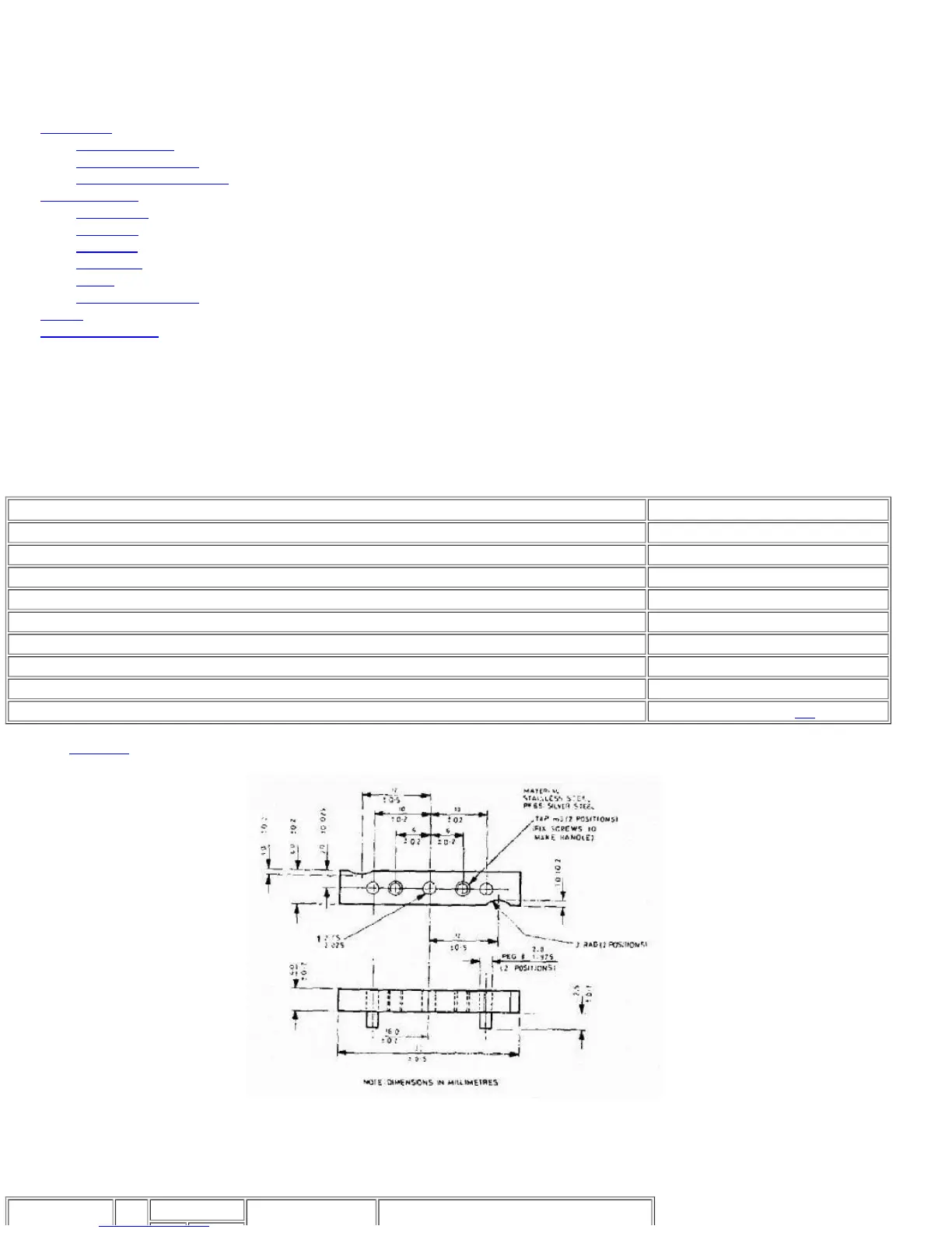
Motor location jig See Figure 4.1
1.1.2 See Section 5 for the board layouts of the Issue 5 and Issue 6 boards.
FIGURE 4.1 MOTOR LOCATION JIG
1.2 Modification History
1.2.1 The only area that has seen substantive modification is the ROM/EPROM section of the memory. The following table sets out the various fits.
Build Standard IC
ROM/EPROM
Software Standard Remarks