22
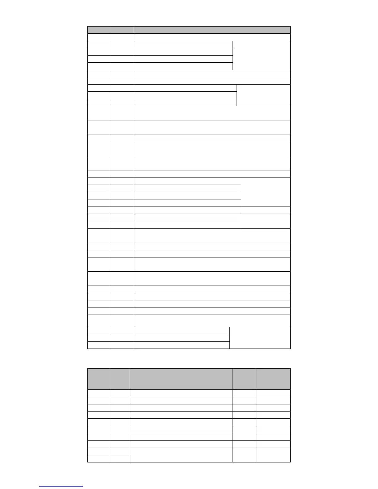
4.4.1 Control signal terminal pin distribution
The positive terminal of command pulse when using 24V power supply
Digital input, the default function number is 7
See section 3.4.2 and
3.4.3
Digital input, the default function number is 5
Digital input, the default function number is 3
Digital input, the default function number is 1
+ 5V power supply, maximum output current 50mA.
Power supply ground (+ 24V)
Digital output, the default function number is 1
See section 3.4.2 and
3.4.4
Digital output, the default function number is 8
DO4 digital output COM terminal
Z pulse positive frequency dividing output, the maximum current is
20mA.
B pulse positive frequency dividing output, the maximum current is
20mA.
A pulse negative frequency dividing output
Analog input signal ground
Analog input, input impedance: 10kΩ, the maximum input voltage ±
12V.
The positive terminal of command pulse when using 24V power supply
Digital input, the default function number is 8
See section 3.4.2 and
3.4.3
Digital input, the default function number is 6
Digital input, the default function number is 4
Digital input, the default function number is 2
Digital input common positive terminal
Digital output, the default function number is 2
See section 3.4.2 and
3.4.4
Digital output, the default function number is 12
Internal 24V power supply, voltage range of + 20V ~ 26V.
The maximum output current is200mA.
Encoder Z pulse negative output
Encoder B pulse negative output
Encoder A pulse positive output.
The maximum current is 20mA.
Analog input. The input impedance is 10kΩ,
The maximum allowable input voltage is ± 12V.
Position direction command +
Position direction command -
Encoder Z pulse open collector output.
The maximum allowable input current is 40mA.
COM digital output terminal of DO1
See section 3.4.2 and 3.4.4
COM digital output terminal of DO2
COM digital output terminal of DO2
4.4.2 Digital Input \ Output Terminal Description
Corresponding
function code
Servo motor power on enable
Position control pulse deviation counter clear
Speed instruction direction selection
Internal instruction bit0
Internal instruction bit1
Internal instruction bit2
Internal instruction bit3
Servo ready output signal
The maximum allowable output current 40mA
 Loading...