Corresponding
function code
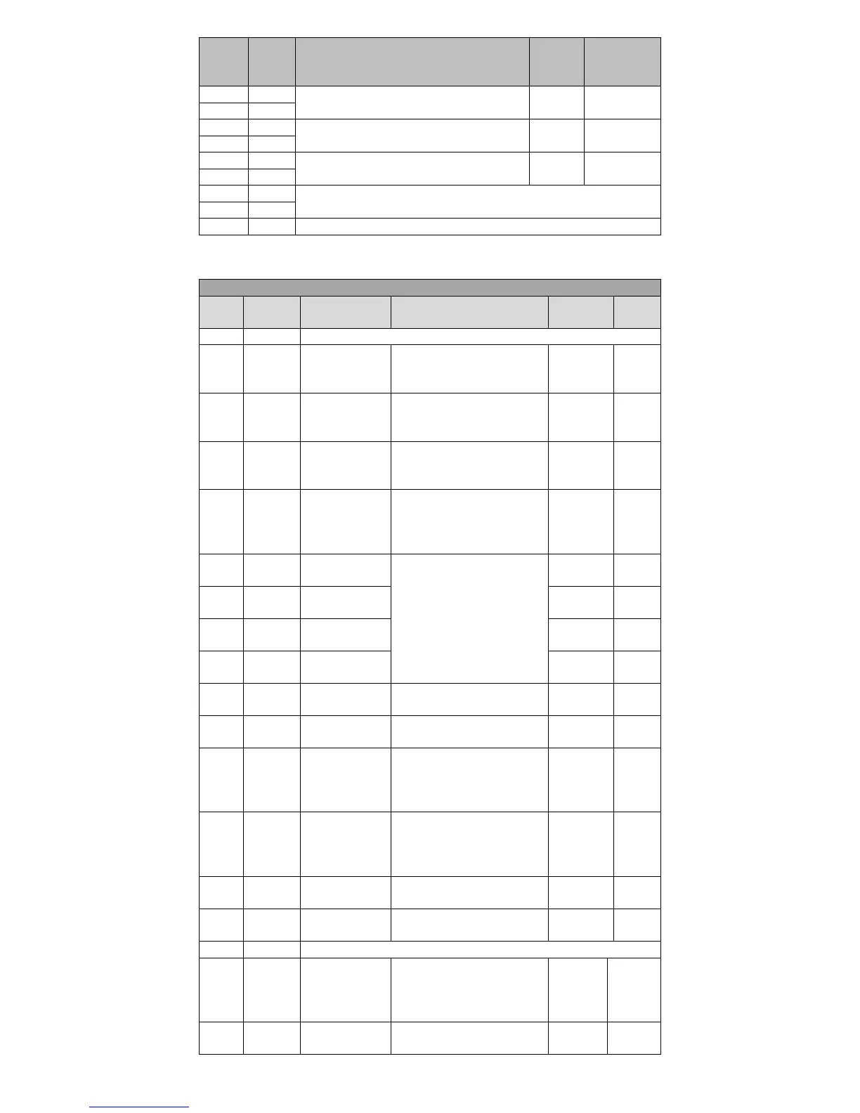
Brake output signal
The maximum allowable output current 40mA
Rotation of the motor output signal
The maximum allowable output current 40mA
Output signal stops servomotor
The maximum allowable output current 40mA
Internal 24V supply voltage range + 22V ~ 26V, 200mA maximum output
current
Digital input common positive terminal(12V~24V)
4.4.3 Digital input (DI) function definition table
Input Signal Function Description
ON- Servo motor power enable
OFF- Servo motor cancel
enabled
ON- If the abnormal condition
have been solved, resettable
fault can be reset.
Position control
pulse deviation
counter clear
See P1-34 for definition of
trigger
Speed command
direction
selection
ON- Instruction in the opposite
direction
OFF- Default command
direction
Internal
instruction bit0
When works in position control
mode, it is location
multi-segment switching
function signal;
When works in speed control
mode, it is speed multi-segment
switching function signal;
Internal
instruction bit1
Internal
instruction bit2
Internal
instruction bit3
Internal
instruction trigger
Multi- segment position trigger
condition
Used for mixed control mode
switch
Analog speed
command zero
fixed enable
ON- Zero fixed function
enabled
OFF- Zero fixed function
disenabled
ON- Prohibit command pulse
input
OFF- Allow command pulse
input
OFF- Prohibit forward drive
ON- Allow forward drive
OFF- Prohibit Reverse driving
ON- Allow reverse drive
ON- Input in accordance with
the given instruction
OFF- Stop input running
instruction
ON- Input in accordance with
the given instruction
 Loading...