Input Signal Function Description
Valid:Origin return accomplished
Invalid:Origin return not accomplished
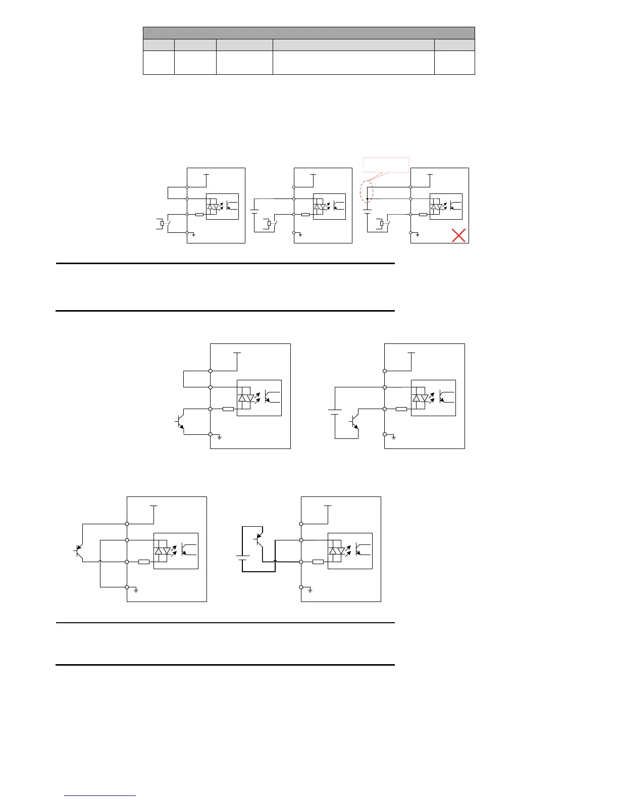
4.4.5 Digital input wiring
The digital input terminals (DI) of EA100 servo drive adopt full bridge rectifier circuit. The current through the terminal can be positive (NPN
mode), or negative (PNP mode). So the external connections of DOI ~ DI8 terminals can be very flexible.
Here is an example of DI1. The interface circuitry of DI1 ~ DI8 is the same.
1) When host device is relay output:
4.7K
+24V
+ 24V
power supply
COM+
DI1
Relay
COM
Servo internal 24V power supply
4.7K
+24V
COM+
DI1
Relay
COM
Servo internal 24V power supply
DC24V
4.7K
+24V
COM+
DI1
COM
Servo drive Servo drive
Do not use a separate
power supply
25
21
5
7
25
21
5
7
25
21
5
7
Relay
DC24V
+ 24V
power supply
+ 24V
power supply
Figure 4-8 Digital input terminal when host device is relay output
Remark:Some of manual defaults are as followed:
COM: 7pin,users can also use 22/36 pin
GND: 14pin,users can also use 29/41/42/43/44 pin
Servo internal +24V: 25pin,users can also use 40pin
2) When host device is NPN open collector output
4.7K
+24V
+24V Power
supply
COM+
DI1
COM
Servo internal 24V power supply
Servo drive
NPN input
NPN
4.7K
+24V
+24V Power
supply
COM+
DI1
COM
Servo internal 24V power supply
Servo drive
NPN input
NPN
DC24V
25
21
5
7
25
21
5
7
Figure 4-9 (a) Digital input terminal when host device is NPN open collector output
3)When host device is PNP open collector output:
4.7K
+24V
+24V Power supply
COM+
DI1
COM
Servo internal 24V power supply
Servo drive
PNP input
PNP
4.7K
+24V
+24V Power
supply
COM+
DI1
COM
Servo internal 24V power supply
Servo drive
PNP input
PNP
DC24V
25
21
5
7
25
21
5
7
Figure 4-9(b) Digital input terminal when host device is PNP open collector output
Remark:
1. Be sure that the 24V and COM + terminals are not connected when using an external power
supply.
2. PNP and NPN input cannot be used mixedly
4.4.6 Digital output wiring
Here is an example of DO1. The interface circuitry of DO1 ~ DO4 is the same.
1) When host device is relay input:
 Loading...