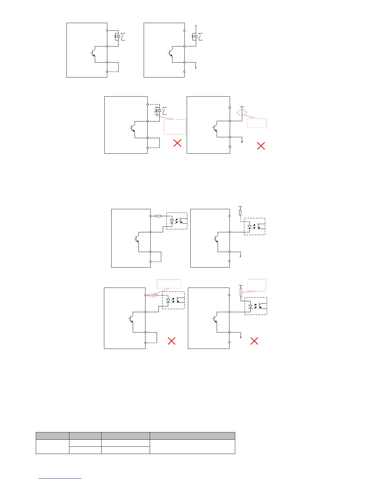
Figure 4-10(b) incorrect digital input wiring when host device is relay output
Remark:
When the host device is relay input, make sure to access the freewheeling diode, or it may damage the DO port.
2) When the host device is optocoupler input
Figure 4-11(b) incorrect digital input wiring when the host device is optocoupler input
Remark:
The maximum allowable voltage, current capacity of servo drive internal optocoupler output circuit is as followed:
Voltage:DC30V(maximum)
Current: DC 50mA (maximum)
If driving the inductive loads (relay, contactor), a surge voltage absorption circuit should be added; such as RC absorption circuit (the
leakage current should be less than the holding current of contactor or relay) varistor, or freewheeling diode (for DC circuit, check the
polarity during installation). The element of snubber circuit should be closed to the relay or contactor.
4.4.7 CN4 analog input terminal wiring
Table 4-4 analog input terminal description
 Loading...