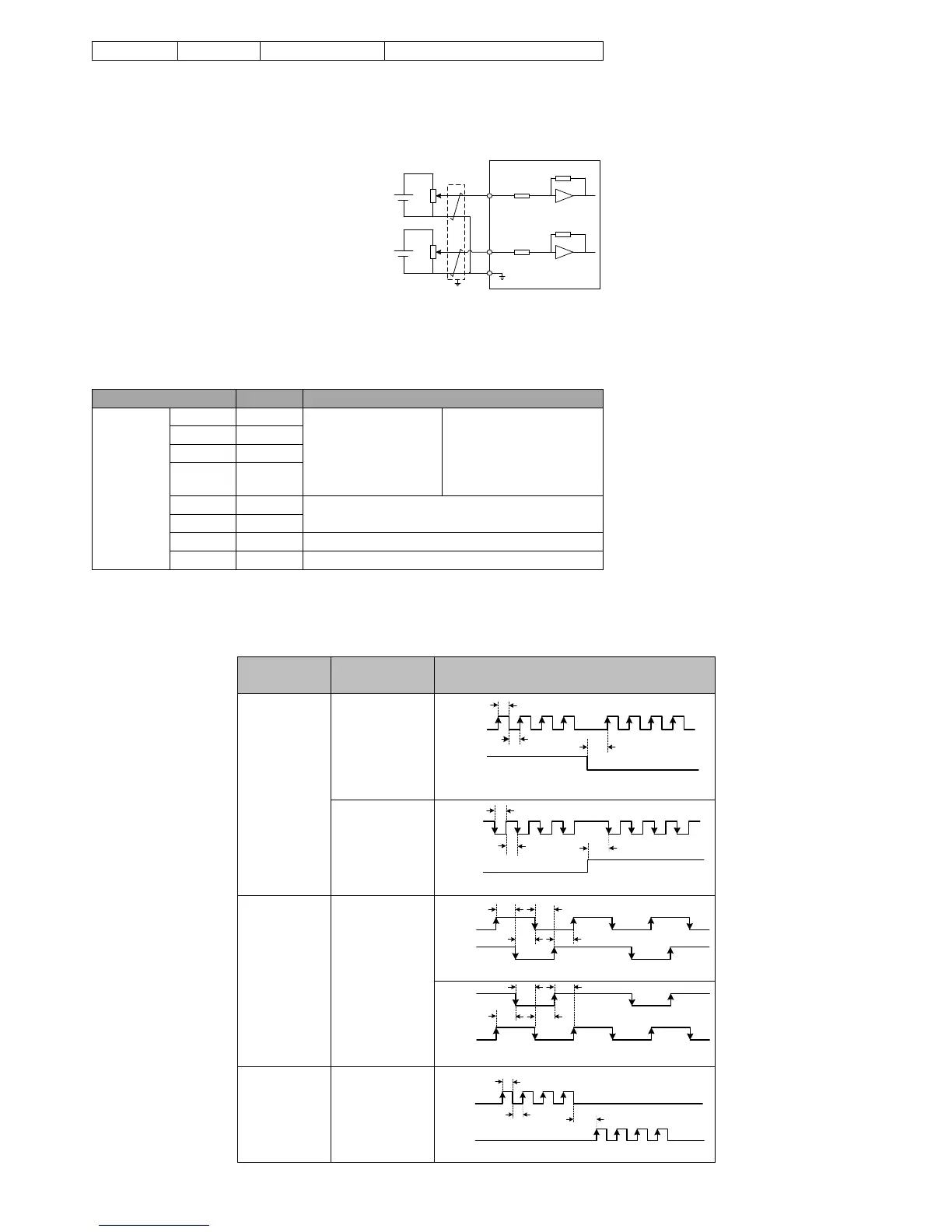
AI1, AI2 generally used for speed and torque analog signal input。
Input voltage range:-10V~+10V, resolution 12 bit;
Maximum allowable voltage:±12V;
Input impedance:10K;
-10~+10V
AI1
-10~+10V
AI2
About 9K
About 9K
Servo motor
GND
15
30
29
Figure 4-12 AI1, AI2 terminal wiring diagram
4.4.8 CN4 position command input signal
Describe for position command pulse input signal, the instruction symbol input signal terminal of CN4 are as followed.
Table 4-4 position pulse input signal specifications
Pulse command input:
Differential Input
Open collector input
Input pulse shape:
Direction + pulse
A, B phase orthogonal
pulse
CW/CCW pulse
External power input interface of command pulse
Pulse command can be input by open collector input or differential input. The maximum differentia input pulse wave is 500Kpps, maximum
open collector input pulse wave is 200Kpps.
Different forms of command input pulse has different timing parameters,see section table 3-5 table 3-6 for details:
Table 4-5 different command pulse timing table
PULSE
SIGN
T3
T2
Forward
Reversal
T1
PULSE
SIGN
T3
T2
Forward
Reversal
T1
Two-phase
orthogonal
pulses (4times)
PULSE
SIGN
T4 T4
Forward
T4
T4
Reversal
PULSE
SIGN
T4
T4
T4
T4
PULSE
SIGN
T3
T1
T2
Forward Reversal
 Loading...