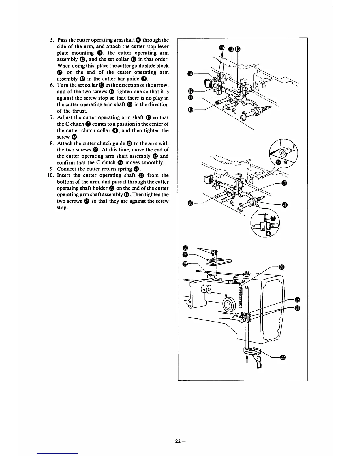
5. Pass thecutter operating arm shaft 0 through the
side
of
the
arm,
and
attach
the
cutter
stop
lever
plate mounting
O'
the cutter operating arm
assembly
0,
and the set collar 0 in that order.
When doing this, place the
cutter
guideslide block
0 on the end of the cutter operating arm
assembly 0 in the cutter bar guide
0.
6. Turn the set collar0 in the direction of the arrow,
and of the two screws 0 tighten one so that it is
agianst the screw stop so
that
there is no play in
the cutter operating arm shaft 0 in the direction
of
the
thrust.
7. Adjust the cutter operating arm shaft 0 so that
the C clutch 0 comesto a position inthe center of
the cutter clutch collar
O,
and then tighten the
screw
0.
8. Attach the cutter clutch guide 0 to the arm with
the two screws
0.
At this time, move the end of
the cutter operating arm shaft assembly 0 and
confirm that the C clutch 0 moves smoothly.
9 Connect the cutter return spring
0.
10. Insert the cutter operating shaft 0 from the
bottom
of
the
arm,
and
pass it
through
the
cutter
operating shaft holder 0 on the end of the cutter
operating arm shaft assembly
0.
Then tighten the
two screws 0 so that they are against the screw
stop.
0
-22-
0
0