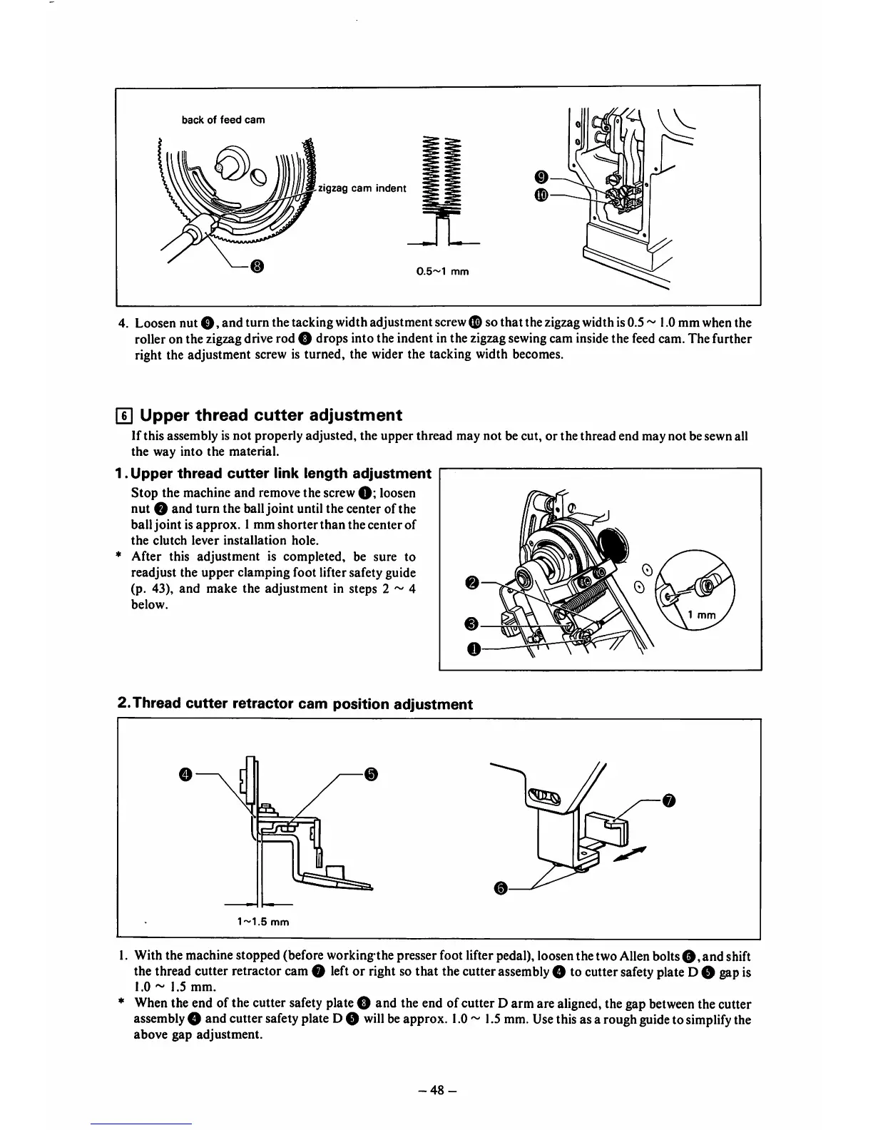
back
of
feed
cam
zigzag
cam
indent
0.5~1
mm
4. Loosen nut
O,
and turn thetackingwidthadjustment screw
(S)
so that the zigzagwidthis0.5 1.0mmwhenthe
roller on the zigzagdrive rod O drops into the indent in the zigzagsewingcam insidethe feedcam. The further
right the adjustment screw is turned, the wider the tacking width becomes.
U]
Upper
thread
cutter
adjustment
If this assembly is not properly adjusted, the
upper
thread
may not be cut, or the thread end may not be sewn all
the way into the material.
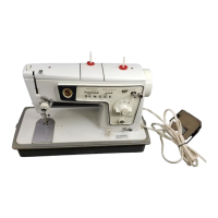
1.
Upper
thread
cutter
link
length
adjustment
Stop
the machine
and
remove the screw loosen
nut o and turn the balljoint until the center of the
ball joint is approx. 1mm shorterthan the centerof
the
clutch
lever
installation
hole.
♦
After this adjustment is completed, be sure to
readjust the upper clamping foot lifter safety guide
(p. 43),
and
make
the adjustment in steps 2 ~ 4
below.
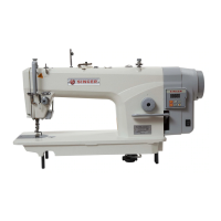
2.Thread
cutter
retractor
cam
position
adjustment
0
1.5
mm
1. With the machine stopped (before working the presser foot lifter pedal), loosen the two Allen bolts
©,
and
shift
the threadcutter retractorcamo leftor rightso that thecutter
assembly
O to cutter
safety
plateD 0 gapis
1.0
~
1.5
mm.
♦
When
the end ofthe cutter
safety
plateO and the end ofcutter Darm are
aligned,
thegap
between
thecutter
assembly
O andcutter
safety
plateD0
will
beapprox.
1.0
~
1.5
mm.
Use
thisasa rough
guide
to
simplify
the
above
gap
adjustment.
-48-