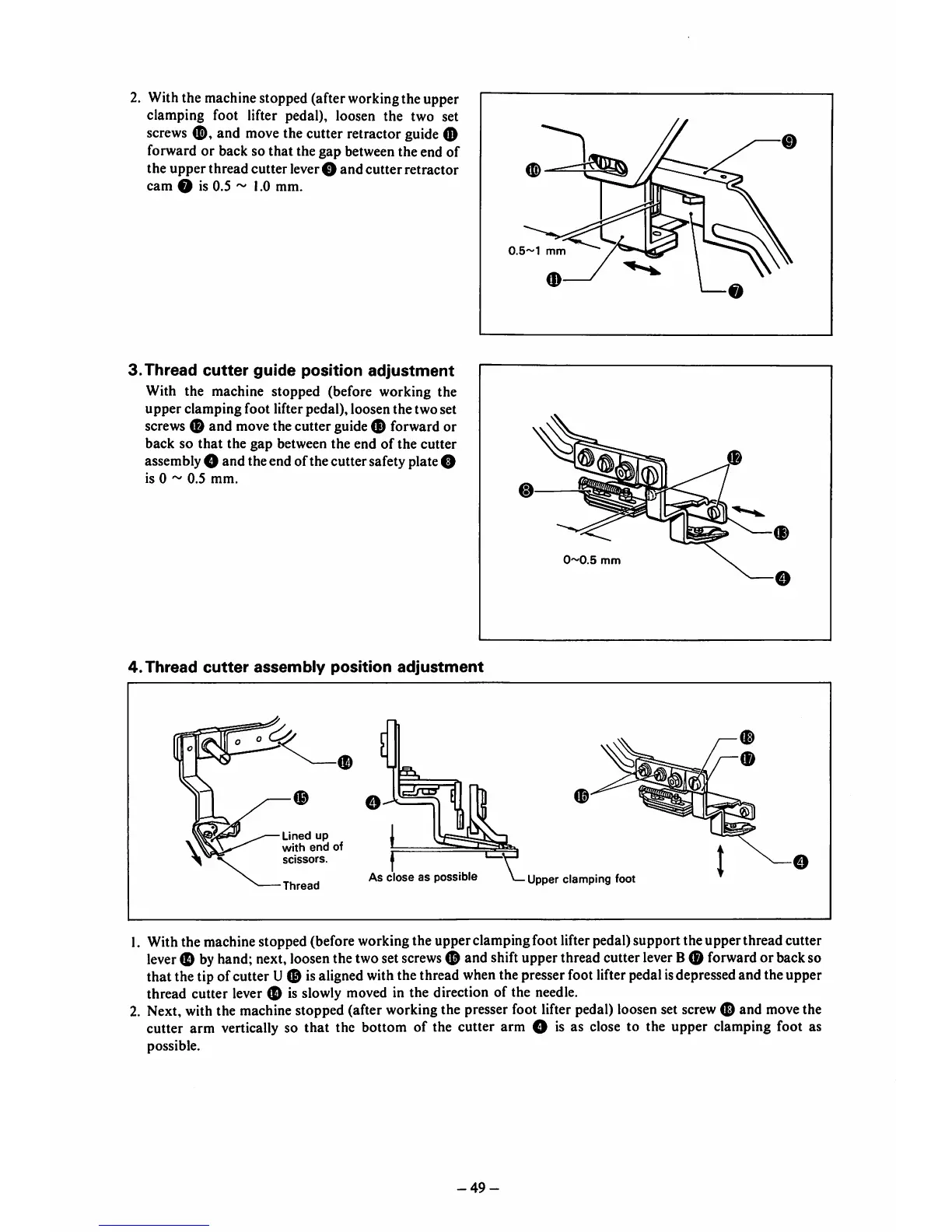
2. Withthe machinestopped (after workingthe upper
clamping foot lifter pedal), loosen the two set
screws
and
move the cutter retractor guide 0
forward or back so that the gap between the end of
the upperthread cutter lever O
and
cutter
retractor
cam O is 0.5 ~ 1.0 mm.
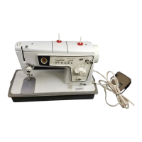
3.Thread
cutter
guide
position
adjustment
With the machine stopped (before working the
upper
clamping
foot
lifter pedal), loosen
the
two
set
screws 0 and movethe cutter guide 0 forward or
back
so
that
the
gap
between the end
of
the
cutter
assemblyO and theend ofthecutter safetyplateO
is 0 ~
0.5
mm.
/—®
0.5~1
mm
0
^ \
—0
I
0~0.5
mm
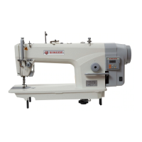
4.
Thread
cutter
assembly
position
adjustment
2.
0
Lined
up
with
end
of
scissors.
Thread
O
c=DTP'
As
close
as
possible
Upper clamping foot
With the machine stopped (before working the upper clamping foot lifter pedal) support the upperthread cutter
lever
0 byhand;next,
loosen
thetwoset
screws
0 and shiftupperthreadcutter
lever
B0
forward
or backso
that the tip of cutter U© is aligned with the thread when the presserfoot lifterpedalisdepressedand the upper
thread cutter lever 0 is slowly moved in the direction of the needle.
Next, with the machinestopped (after workingthe presserfoot lifter pedal) loosenset
screw
0 and movethe
cutter arm vertically so that the bottom of the cutter arm O is as
close
to the upper clamping foot as
possible.
-49-