II.
12.
13.
14.
15.
16.
17.
18.
19.
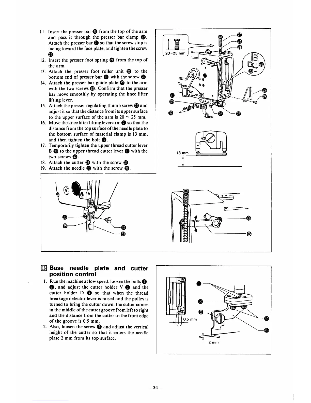
Insert the presser bar 0 from the top of the arm
and pass it through the presser bar clamp
Attach the presser bar ® so that the screwstop is
facing toward the face plate, and tighten the screw
0.
Insert the presser foot spring ® from the top of
the
arm.
Attach the presser foot roller unit ® to the
bottom end of presser bar 0 with the screw
©.
Attach the presser bar guide plate ® to the arm
with the two screws
®.
Confirm
that
the presser
bar
move
smoothly
by operating the knee lifter
lifting lever.
Attach the presser regulating thumb screw0 and
adjust it so
that
the distance from its uppersurface
to the upper surface of the
arm
is 20 ~ 25 mm.
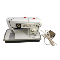
Move the knee lifter lifting leverarm O so thatthe
distance from
the
top
surface
of
the needle plate to
the
bottom
surface
of
material
clamp
is 13
mm,
and then tighten the bolt
O.
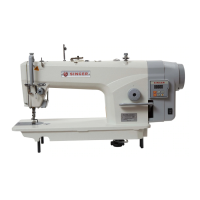
Temporarily
tighten the
upper
thread
cutter
lever
B 0 to the upper thread cutter lever 0 with the
two screws
0.
Attach the cutter 0 with the screw
0.
Attach the needle 0 with the screw
0.
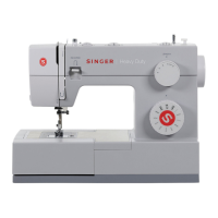
in]
Base
needle
plate
and
cutter
position
control
1.
Run
the machineat low speed, loosen
the
bolts
0,
and adjust the cutter holder V 0 and the
cutter holder D O so
that
when the thread
breakage detector lever is raised
and
the pulley is
turned
to
bring
the
cutter
down,
the
cutter
comes
in the middle of the cuttergroove from left to right
and
the distance from the cutter to the front edge
of
the
groove
is 0.5
mm.
2. Also, loosen the screw 0 and adjust the vertical
height
of
the
cutter
so
that
it
enters
the
needle
plate 2 mm from its
top
surface.
20^^25
mm
V. ^
0
13
mm
0.5
mm
-34-
m
0
0
@
2
mm