tool is not involved in the processing, so, you must enter (TL DIA) =0.
6. Enter the maximal cut (MAX CUT)
When this function is used in the processing of circular arc, the cut of
every cutting feed is uniform, as shown in Fig. (d).
7. Enter the start angle of the circular arc (ST ANG)
This determines the position of the first cut feed in the processing of
circular arc. As show in Fig.(b), the start angle is 0° if the arc is to be
processed from Point E to Point F, and 90° when from F to E.
8. Enter the end angle of the arc (ED ANG)
This determines the position of the last cut feed in the processing of
circular arc. As shown in Fig. (b), the end angle is 90° if the arc is to be
processed from Point E to Point F, but 0 when from F to E.
9. Determine inner/outer circle mode:
For outer circular arc, as shown in Fig. (b), RAD+TL.
For inner circular arc, as shown in Fig. (c), RAD -TL.
10. Move the machine tool to the start point of the processing in
following with the display on axes, and then start the point by point
processing.
11. You can quit the Arc R Calculation function as will, just key .
(
Ù
ÙÙ
Ù
) *Take the processing of the arc shown in the figure in page 22 as an
example (Example 1)
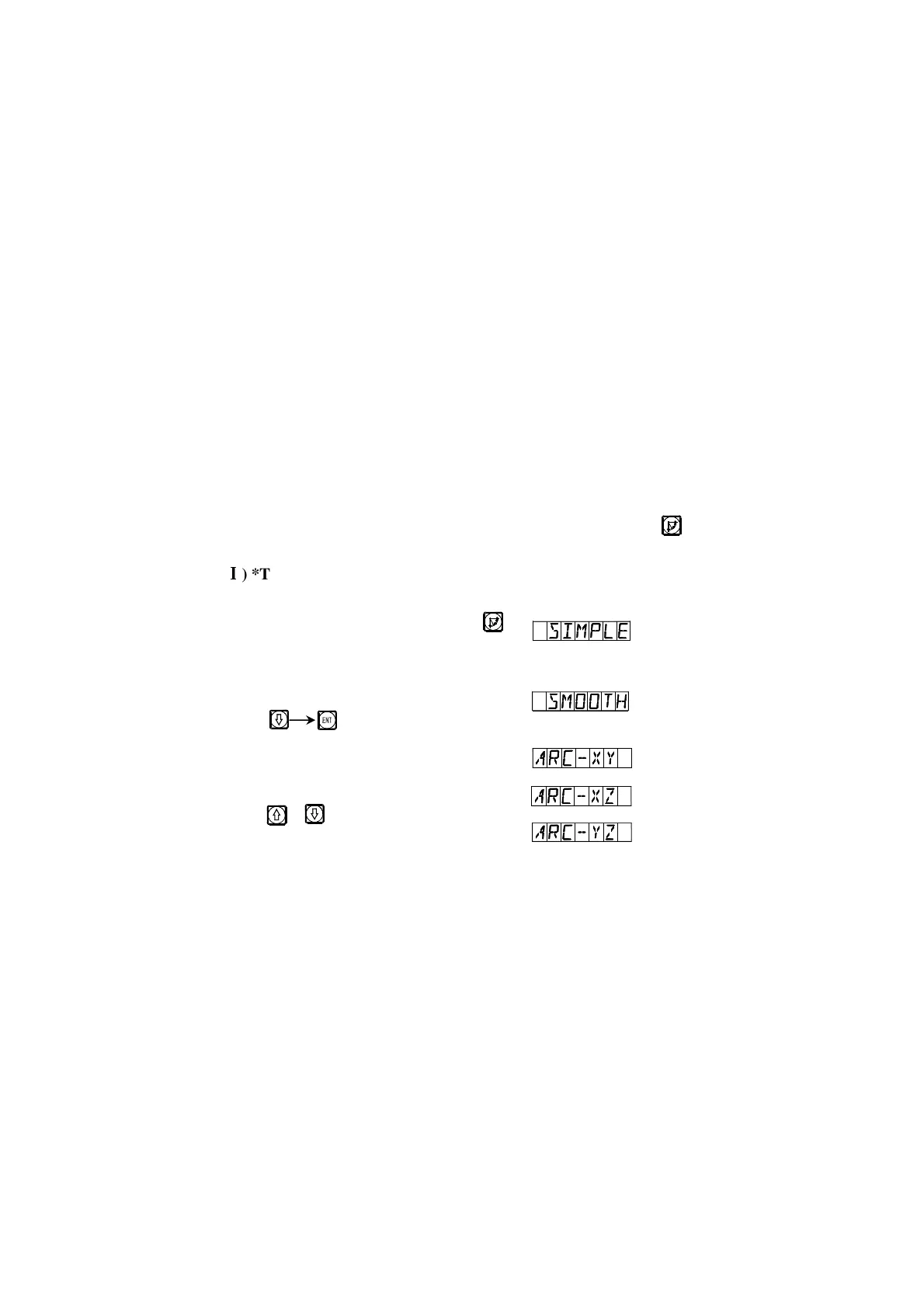
1) At first, finish tool setting, reset, key ,
and enter ARC function.
2) Select smooth function.
Key
3) Select processing plane
Key or
R
R
 Loading...