© Jun. 2021 6-12 1323RE&1623RE Operation Manual
PRE-OPERATION FUNCTION TEST
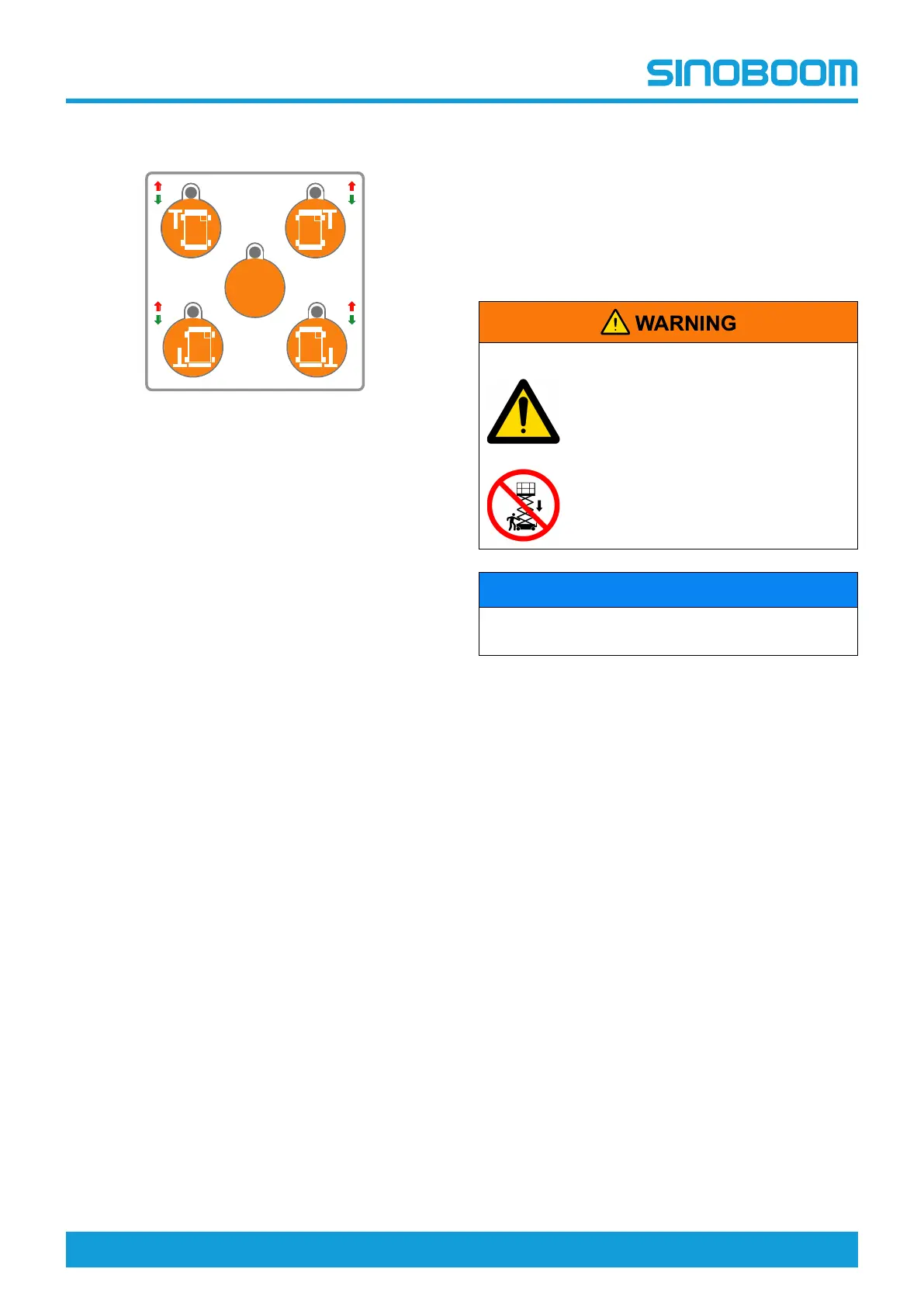
OUTRIGGER LEVELING
1. Press the outrigger self-level switch, hold the
joystick enable switch and slowly pull backward
the joystick.
2. The outriggers should extend to the ground and
level the machine, and the indicator light should
be lit after the machine becomes level.
3. Press the outrigger self-level switch, and hold the
joystick enable switch and slowly push forward
the joystick.
4. The outriggers should retract, and the indicator
light should go out.
5. Press the individual outrigger level switch, and
hold the joystick enable switch and slowly pull
backward the joystick.
6. The corresponding outrigger should retract and
the indicator light should be lit after the outrigger
touches the ground.
7. Press the individual outrigger level switch, and
hold the joystick enable switch and slowly push
forward the joystick.
8. The corresponding outrigger should retract and
the indicator light should go out.
TESTING THE EMERGENCY
LOWERING FUNCTION
1. Turn the Ground/Platform select switch on the
ground controller to the platform control position.
2. Pull out the emergency stop buttons on both the
ground and platform controllers to the ON position.
3. Press the platform lift switch.
4. Hold the joystick enable switch and slowly deflect
forward the joystick to raise the platform to a height
and release the joystick
5. Press simultaneously the both emergency lowering
switches.
6. The platform should lower until properly in place,
and the alarm should sound while the platform is
lowering.
TESTING THE LEVEL
SENSOR
UNSAFE OPERATION HAZARDS
• Don’t put your hands and arms
close to positions where they may
get squeezed.
• If the safety arm is not in the
proper position, don’t work under
the platform or near the scissor
arm.
NOTICE
Do not stand on the platform but on the ground using
the platform controller to perform this test.
1. Position the machine on a level, firm surface. Start
the machine, and the green indicator light on the
level sensor should illuminate.
2. With the machine in stowed position, place 2
wooden blocks near the two front or rear wheels,
then drive the machine upon the wooden blocks.
The wooden block dimension (L×W×H) is
100×50×150mm (4in×2in×5.9in).
3. Switch from drive to platform lift function, and raise
the platform until the lower limit switch disengages,
the red indicator light on the level sensor will
illuminate with the alarm sounding, and further
lifting and driving is restricted.
4. Lower the platform to the stowed position, the alarm
will stop sounding, and the machine function limit is
cancelled.
5. Drive the machine off and remove the wooden
blocks.
6. With the machine in stowed position (outrigger
retracted), place 2 wooden blocks near the two
wheels on the left or right side, then drive the
machine upon the wooden blocks. The wooden
block dimension (L×W×H) is 100×50×70mm
(4in×2in×2.76in).
7. Switch from drive to platform lift function, and raise
the platform until the lower limit switch disengages,
the red indicator light on the level sensor will