© Oct 2020 6-8 AB18EJ&18HJ Maintenance Manual
REPAIR PROCEDURES
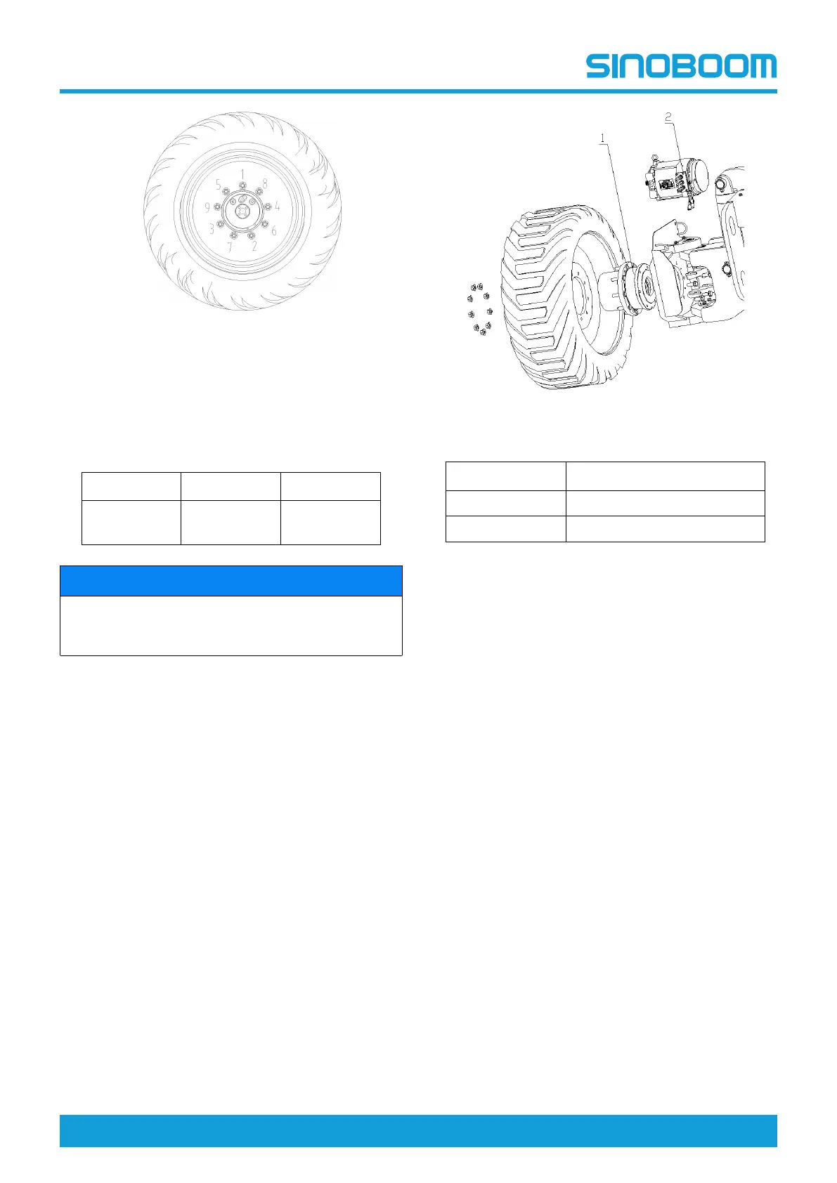
Figure 6-8
3. The tightening of the nuts should be done in stages.
Following the recommended sequence, tighten nuts
per wheel torque as listed in the table below.
Table 6-1
1st Stage 2nd Stage 3rd Stage
150Nm
(110ft-lb)
250Nm
(185ft-lb)
280Nm
(207ft-lb)
NOTICE
Wheel nuts should be torqued prior to first use of
machine and after each wheel removal. Check
torque every 3 months or 150 hours of operation.
Reducer and Drive Motor
The reducer and drive motor act not only the role of
driving the machine but also the role of securing the
rear wheel. Before removing the reducer and motor,
secure the machine on a suitable structure or support
the machine by a jack of ample capacity.
Figure 6-9
No. Description
1 Reducer
2 Drive motor
Removal of reducer and drive motor
1. Place the machine on a solid, level surface.
2. Place a jack of sufficient capacity under the side of
chassis to be removed. Lift the jack to make the
wheel off the ground.
3. Remove the bolts and washers securing the wheel
to the reducer. Use a suitable lifting device to
remove the wheel.
4. Tag, disconnect and plug the hyrdaulic hoses to the
drive motor.
5. Remove the flange to secure the reducer and the
fasteners to secure the outrigger, and lift the flange
and reduce that are removed clear of the base
frame.
6. Remove the flange for motor installation from the
reducer. Take care not to damage the O-ring.
7. Remove the bolts securing the flange to the
reducer.
8. Remove the bolts securing the flange to the drive
motor.
Installation of reducer and drive motor
1. Use a lifting device with sufficient capacity to
support the outrigger.
2. Install the drive motor, and use torque wrench to
secure the bolts in diagonal sequence.
3. Align the reducer brake oil port with the nick of
support.