© Oct 2020 6-10 AB18EJ&18HJ Maintenance Manual
REPAIR PROCEDURES
Installation of slewing bearing
1. Use a lifing device with sufficient capacity to lift the
slewing bearing over the mounting surface of
chassis.
2. Use a feeler gauge to measure the clearance
between the mounting surface of the slewing
bearing and that of the chassis, ensure the
clearance≤0.2mm (0.008in).
3. Using the special washer for the high-strength bolt,
mate the washer surface with the mounting surface,
apply threadlocker Loctite 272 to the bolt, and intall
the bolts one by one.
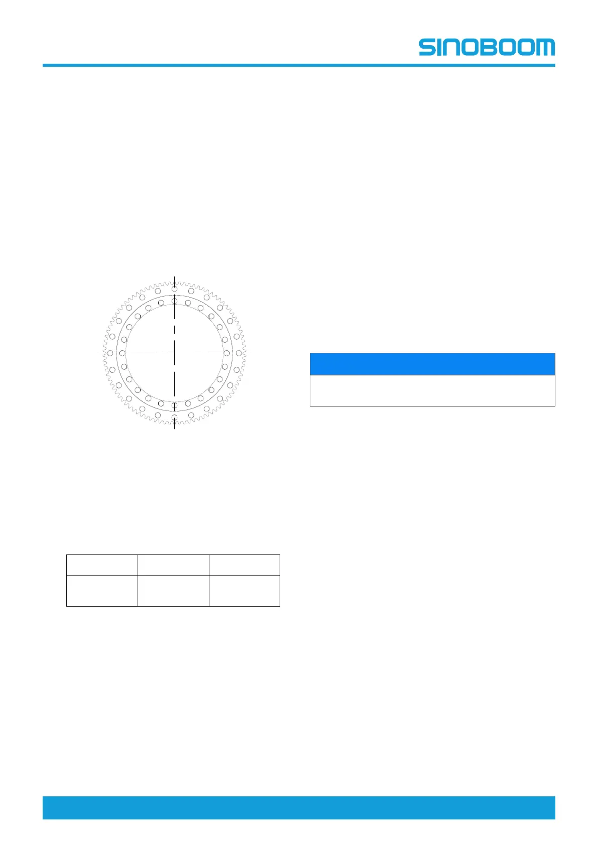
4. Tighten the bolts in the sequence as shown in the
figure below.
Figure 6-12
5. The tightening of bolts should be done in stages,
Follow the stages and the recommended torques as
listed in the table below to tighten the bolts.
Table 6-3
1st Stage 2nd Stage 3rd Stage
90Nm
(66ft-lb)
180Nm
(133ft-lb)
300Nm
(221ft-lb)
6. Hand turn the inner ring of the slewing bearing,
ensure it moves smoothly.
7. Detach the lifting device from the slewing bearing.
8. Rotate the inner ring of the slewing bearing until the
soft strap area on the inner ring and that on the
outer ring are symetrically arranged around the
center of the slewing bearing.
9. Using a lifting device, lift the turntable to the
mounting surface of the slewing bearing.
10. Using the special washer for the high-strength bolt,
mate the washer surface with the mounting surface,
apply threadlocker Loctite 272 to the bolt, and intall
the bolts one by one.
11. Refer to Fig 6-11 , page 6-10,and tighten the
retaining bolts in the sequence as indicated.
12. Refer to Table 6-3 , page 6-10, and tighten the
bolts per the recommended torques and sequence.
Battery
NOTICE
Before removing the battery, be sure to cut off the
charger power source and the total power source.
The batteries are located on both sides of the turntable.
1. Open the turntable cover and locate the battery.
2. Tag and disconnect the battery cables.
3. Remove the battery with lifting assistance.
1
2
3
4
5
6
7
8
9
10
11
12
13
14
15
16
17
18
19
20
21
22
23
24