INSTALLATION AND OPERATING INSTRUCTIONS
SKF Multilog On-line System IMx-16Plus
SKF Multilog On-line System IMx-16Plus
User Manual
Revision Letter A
connection. DNS lookup of server name and NTP time synchronisation, are
supported.
Mobile data functionality requires an activated SIM card or eSIM. Wi-Fi and mobile
data functionality require an external antenna to be provided. Note that when
inserting a physical micro-SIM into the SIM card slot the orientation must be as
follows:
• Contacts down and with the card notch across the right and outer edges
• For orientation purposes, note the slot identification lettering ‘SIM’ is above
the slot.
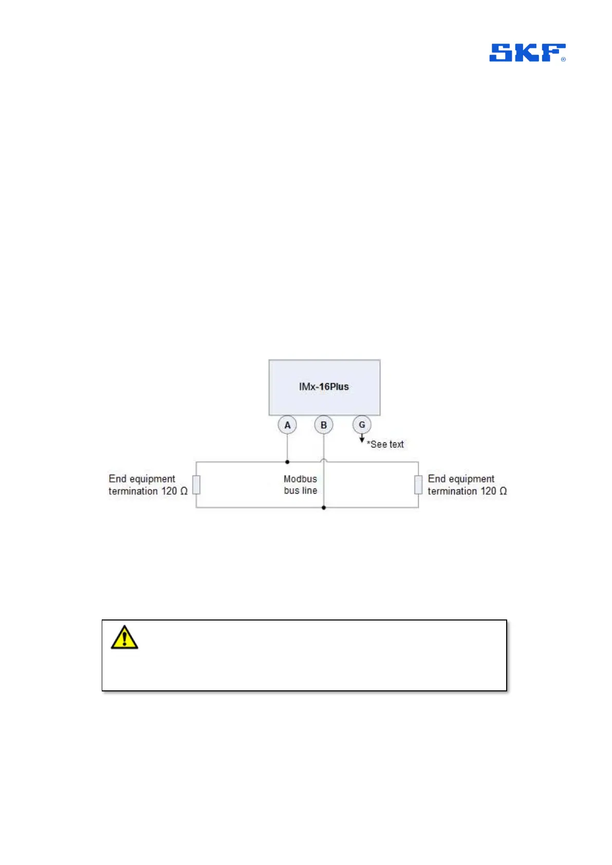
2.5.5 RS485 Modbus connections
The IMx-16Plus has one, 2-wire, RS485 port. For this there are considerations
related to grounding and bus termination, Figure 7.
Figure 7 Modbus Bus Connection and End Termination.
*G (Ground): Devices connected to the bus must have the same ground potential.
When ‘floating’ equipment is connected to the IMx-16Plus bus, the G connection can
be used to ensure the same ground potential. Normally, all devices are connected to
the same ground connection.
If an IMx-16Plus device is placed first or last in the bus chain, then an external bus
termination resistor must be connected to it. (Note: there is no built-in termination that
can be activated by configuration).
Important - To avoid ground loops, ensure that there is only one ground
connection. The IMx-16Plus device’s G (Ground) connector can be used in cases
where the connected equipment bus is floating.