PRODUCT SPECIFICATIONS
Connector details
SKF Multilog On-line System IMx-16Plus
User Manual
Revision Letter A
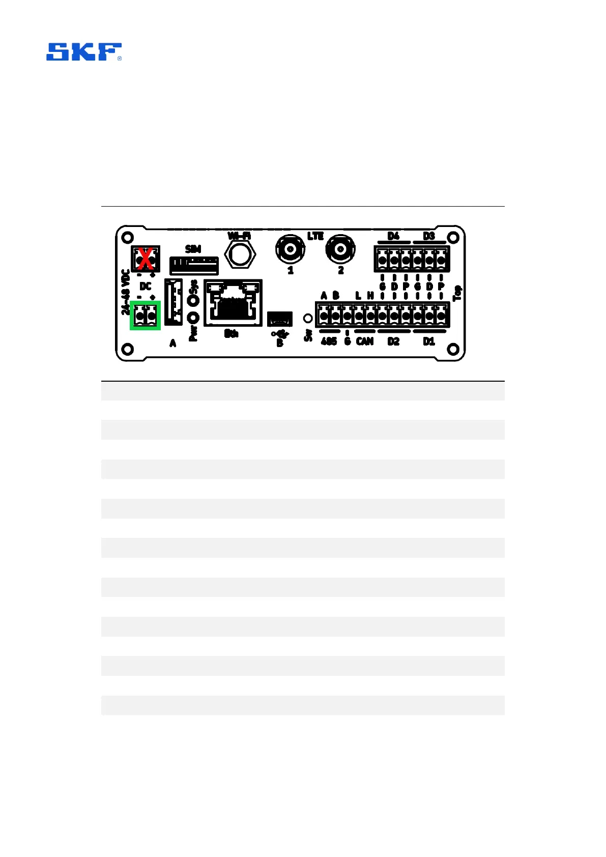
3.3 Connector details
3.3.1 IMx-16Plus top end cap
Table 5 IMx-16Plus top end cap connections
± for 24-48 V DC supply (connect to lower pair, see 2.3).
Micro-SIM card slot (refer 2.5.4 for SIM card orientation)
USB A, host interface (Bluetooth dongle normally fitted here)
RJ45 Ethernet connector (support for Power over Ethernet)
Connector for an external antenna (where Wi-fi, used)
USB mini-B connector, service interface
Mobile data connectors for external antenna (where LTE, used)
RS485 2-wire A and B terminals
Ground connection for use as required by RS485 and/or CAN
CAN bus for vehicle systems (No current firmware support)
4 digital inputs (Ground, Digital, Power terminals for each)
Pwr – Power (green, normal: on), Sys – System (red, normal: off)
Switch/push button - rescue button (enters maintenance mode)
Demountable terminal connectors
For the top connectors, one 11-way, one 6-way and one 2-way are provided.