INSTALLATION AND OPERATING INSTRUCTIONS
SKF Multilog On-line System IMx-16Plus
SKF Multilog On-line System IMx-16Plus
User Manual
Revision Letter A
SKF provide 250-ohm load resistors for this purpose and double deck connectors to
facilitate the installation. These SKF provided resistors must be used and are colour-
coded blue, refer Figure 11.
Figure 11 250-ohm resistor for a 4-20 mA signal
Note: All ground terminals (G1 – G16) of the analogue inputs are connected to each
other, to secure a common ground level. As all channels are referenced to
chassis/enclosure ground, take care to avoid ground loops!
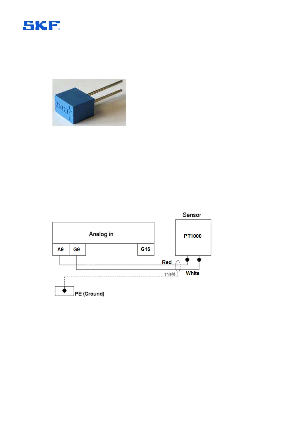
2.5.10 Connecting PT1000 sensors (A9 to A16)
The SKF Multilog IMx-16Plus supports 2-wire PT1000 temperature sensors on the
last 8 channels (A9 to A16). They should be connected as shown in Figure 12 below.
Figure 12 Example connection of a PT1000 sensor to analogue input 9
Note, that the PT1000 sensor lead wires (red and white) are not polarity sensitive
and can have reversed connections to the IMx-16Plus, without any impact on the
measurement function.
Also, note that the IMx-16Plus provides the required sense current for the
measurement and that this is enabled by @ptitude Observer software, automatically
when sensor type PT1000 (C or F) is selected.