INSTALLATION AND OPERATING INSTRUCTIONS
SKF Multilog On-line System IMx-8/IMx-8Plus
SKF Multilog On-line System IMx-8/IMx-8Plus
User Manual
Revision E
2.5.7 Connecting accelerometers (A1 to A8)
The SKF Multilog IMx-8/IMx-8Plus support 2-wire accelerometers on all 8 channels.
The standard accelerometer power can be enabled/disabled by software
configuration. Refer to the @ptitude Observer User Manual for further information.
Connect each accelerometer to the relevant input terminals on the appropriate
analogue connector located on the bottom end cap of the IMx, refer IMx-8 or
IMx-8Plus.
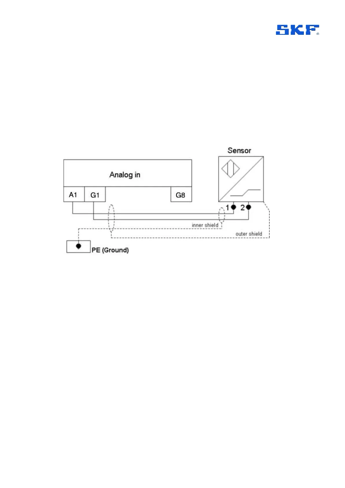
For example, Figure 11, if using analogue channel A1, connect sensor output 1
(signal) to input A1 and sensor output 2 (common/return) to input G1.
Figure 11 Example connection of an accelerometer to analogue input 1
Above, Figure 11, illustrates a typical example where the accelerometer has an inner
screen or shield (isolated from the sensor body – to be grounded at the IMx) and an
outer braid, armour or shield (connected to the sensor body and grounded at the
machine – to be left floating at the IMx).
2.5.8 Connecting voltage sources (A1 to A8)
For voltage sources, 2-wire unpowered sensors or 3-wire accelerometers that are
externally powered, follow the guidance for accelerometers, in 2.5.7, to connect the
signal and common/return lines but in this case, configure the sensor power off.
2.5.9 Connecting 4–20 mA signals (A1 to A8)
To connect 2-wire 4-20 mA signals, configure the sensor supply off: note the IMx
does not power the loop. To convert the current value to a voltage that the IMx can
measure, a load resistor must be used on the input to each channel that a 4-20 mA
signal is connected to.
SKF provide 250-ohm load resistors for this purpose and double deck connectors to
facilitate the installation. These SKF provided resistors must be used and are colour-
coded blue, refer Figure 12.