PRODUCT SPECIFICATIONS
Connector details
SKF Multilog On-line System IMx-8/IMx-8Plus
User Manual
Revision E
3.3 Connector details
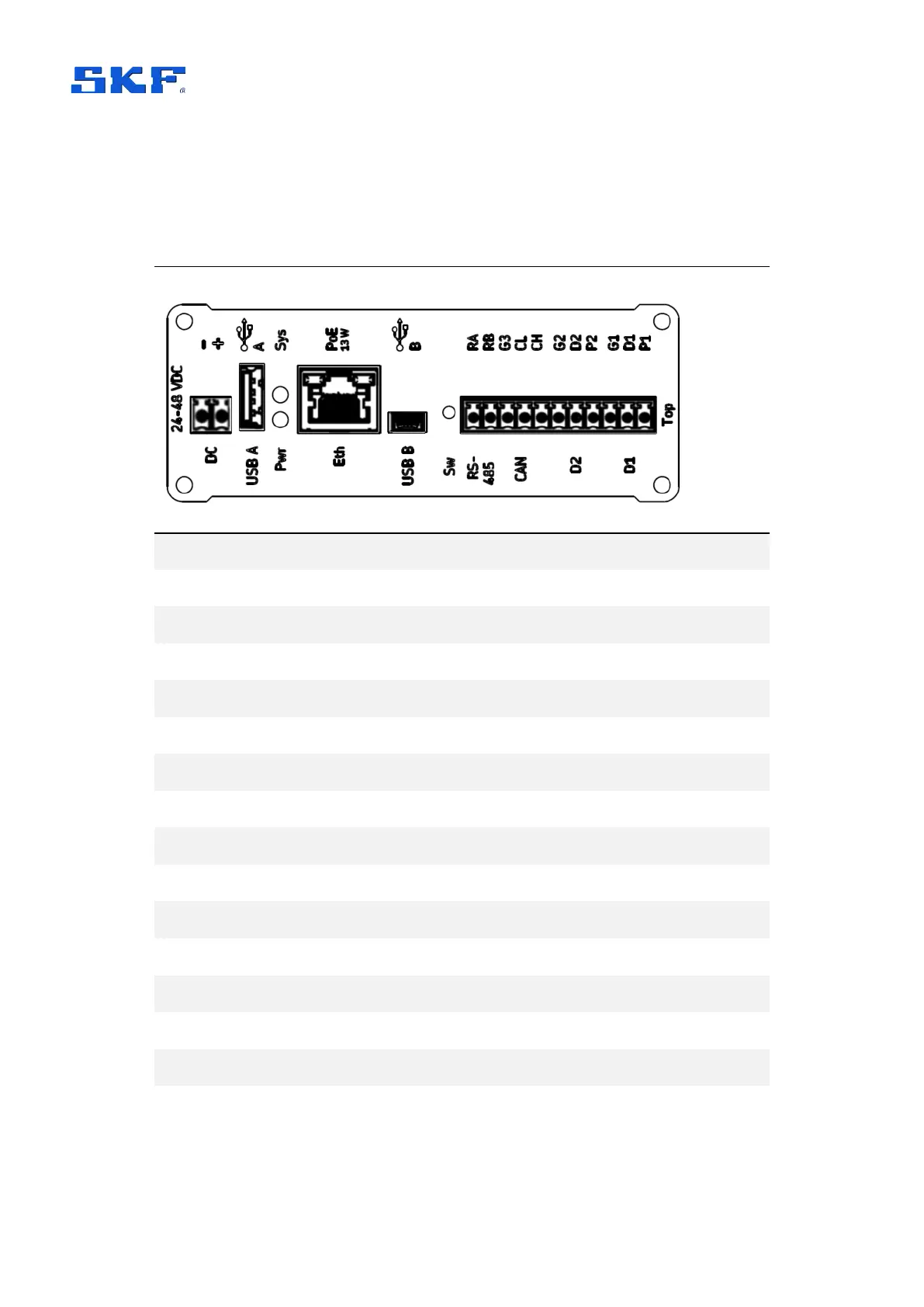
3.3.1 IMx-8 top end cap
Table 6 IMx-8 top end cap connections
USB A, host interface, Bluetooth dongle normally fitted here
RJ45 Ethernet connector with support for Power over Ethernet
USB mini-B connector, service interface
RS485 2-wire A and B terminals
Ground connection for use as required by RS485 and/or CAN
CAN bus for vehicle systems – no current firmware support
2 digital inputs (Ground, Digital, Power terminals for each)
Pwr – Power (green, normal: on), Sys – System (red, normal: off)
Switch/push button – rescue button (enters maintenance mode)
Demountable terminal connectors
For the top connectors, one 11-way and one 2-way are provided.