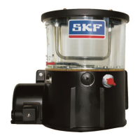
Pump units of the KFGS series for rotary application
151-3034-EN
The KFGS pump unit is controlled by the
IG502-I integrated control and monitoring
unit.
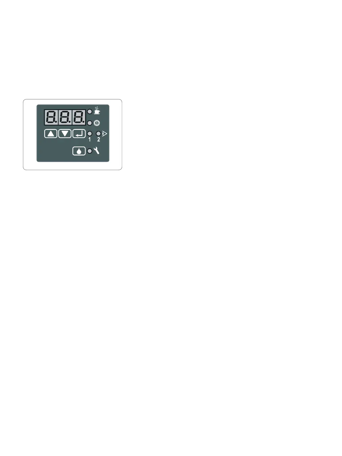
IG502-2-I integrated control and
monitoring unit
Pause (cPA)
in "COUNTER" mode
The pause (duration between two lubrica-
tions) in COUNTER mode is determined based
on the duration of the pulses received at con-
nection DK (signal change from 0 V to 24 V)
and by the value programmed as the cPA. Its
value can be set from 1 to 999 pulses. In this
mode, the DK connection leading from the
unit is used as a clock pulse input to trigger
lubrications after a specified number of puls-
es. In this case, an external pushbutton can-
not be used to trigger interim lubrications.
Setting interval and pump
cycle times and desired
monitoring function
See the operating instructions included with
the pump unit for information on how to con-
figure the control unit for application-specific
values and functions.
Function (Standard "TIMER" function
without monitoring)
The lubrication intervals are repeated cycli-
cally after the set interval (tPA or cPA). The
pump cycle time during a lubrication proce-
dure corresponds to the time configured on
the control panel as tCO (contact time) in
minutes.
Interval and pump cycle times proceed only in
the presence of supply voltage (connection 15
and 31 to 12 V DC or 24 V DC depending on
unit). When the supply voltage is turned off
(power supply on connection 15 is interrupt-
ed), the current interval time is saved and
continued once the supply voltage is turned
on again.
When the monitoring function CS is pro-
grammed (only for centralized lubrication sys-
tems with cycle switch), the piston detector
mounted on a progressive feeder is queried
for a signal during the pump cycle time. At
least one signal change (either ON>OFF or
OFF>ON) is expected from the control unit to
start a new interval time after the pump cycle
time is finished and to continue the opera-
tional sequence as normal. If this signal is ab-
sent during the
preselected pump cycle time (tCO), a monitor-
ing program (block operation) is started after
the cycle time finishes. During this program
sequence, the pump unit is turned on up to
two additional times at specially defined in-
tervals and the piston detector is monitored
for a signal. If the piston detector signal
reaches the control unit, the monitoring pro-
gram ends immediately and operation con-
tinues as normal. If the monitoring program
completes its sequence, a fault notification
is issued on completion and the operational
sequence is halted. While the monitoring pro-
gram is ongoing, no interim lubrications can
be triggered.
Storage (EEPROM)
The control unit has non-volatile memory
(EEPROM), so continuous power supply is not
required to store intervals and fault notifica-
tions. When the supply voltage is turned off,
the current value is saved and will be avail-
able for continued operation once the supply
voltage is re-established.
Monitoring and fault indications
Function monitoring with piston
detector
Centralized lubrication systems can be moni-
tored using piston detectors. To do this, CS
(cycle switch) must be set as the monitoring
in COP when the device is configured (pro-
grammed). The signal from the switch is then
monitored during lubrication. If the signal is
not sent during the lubrication procedure and
the monitoring program it automatically trig-
gers does not start, a fault notification is sent
(connection SL2 is constantly switched on) af-
ter the monitoring program ends, and the op-
erational sequence is interrupted. The error
code FCS (Fault Cycle Switch) can be viewed
by pressing a key on the control panel.
General
The IG502-2-I control and monitoring unit is
an integral component of the KFGS pump
unit. Its functions are specially designed to
control and monitor centralized lubrication
systems. The customer can program the con-
trol unit to adapt it to the particular operating
conditions of the machine/system and set the
following modes:
1. TIMER without monitoring•
2. TIMER with monitoring•
3. COUNTER without monitoring•
4. COUNTER with monitoring•
Pause (tPA)
in "TIMER" mode
The interval (time period between two lubri-
cations) in the TIMER mode is determined
based on a time interval generated by the
control unit and the value programmed as the
tPA. Its value can be set from 0.1 to 99.9 h.
Display

 Loading...