Pump units of the KFG, KFGS and KFGC series for rotary application
4 1-3034-EN
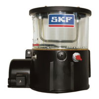
KFGS control unit
Pump units of the KFGS series are equipped
with an IG502-2-I integrated control unit
with a control display. Parameters for interval
times (timer), interval pulses (counter) and
pump cycle times (contact) can be entered
through the control unit.
Design
Pump units of the KFG, KFGS and KFGC (CAN
bus) series are characterized by their compact
construction and are divided into the assem-
blies for pump housing, lubricant reservoir,
control unit and fill level monitoring. A short
description of the individual assemblies fol-
lows below.
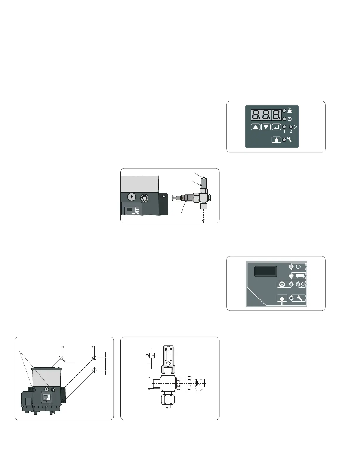
Pressure regulating valve
A pressure regulating valve can be attached to
the pump unit on progressive systems to pre-
vent excessive operating pressure in the lu-
brication system in case of a fault. If the oper-
ating pressure exceeds the cracking pressure
of the pressure regulating valve, the valve
opens and the lubricant flows back (on ver-
sions with a return line) into the lubricant
reservoir.
Assembly holes
A mounting flange with assembly holes is
present on the back of the pump housing on
all pump versions.
Pump element with pressure regulating valve
Pump element
The pump element(s) meter the lubricant
then pass it to the downstream lubrication
points or feeders. Five different pump ele-
ments with a delivery volume ranging from
0.8 to 5 cm
3
/min. are available to provide the
required quantity of lubricant.
Lubricant reservoir
The lubricant reservoir is available in 4 kg, 6
kg, 8 kg, 10 kg and 12 kg sizes. The reser-
voirs are made of transparent plastic and
have fill level markings that allow the fill level
to be monitored visually. Fill level switches
and/or sensors can also be attached.
Pump housing
The pump housing contains, among other
things, the pump drive, control unit (KFGS)
and three lubricant outlets for installing a
maximum of three pump elements. One pres-
sure regulating valve can be attached to each
pump element. When used in single-line sys-
tems, a pressure relief valve with an integrat-
ed pressure regulating valve is attached to the
pump element (max. 1 single-line system per
pump).
A conical head nipple can optionally be at-
tached to the pump housing using the alter-
native connections to fill the pump. A filler
socket or grease return can also be attached.
A display and control screen is mounted on
the front side of the KFGS design, while the
KFGC (CAN bus) design has a display at-
tached. An IRDA interface is integrated into
this, which can optionally be used to program
the pump.
Depending on the pump version and voltage
design, the electrical connections are located
on the left front and/or the underside of the
pump housing.
Assembly holes
Pump element
Pressure
regulating valve
R
A
P
R
M14 x 1,5
P
A
P
A
P
M14 x 1,5
R
R
A
Pressure regulating valve with optional lubricant nipple
KFGS display and control screen
KFGC (CAN bus)
Pump units of the KFGC (CAN bus) series are
equipped with an integrated CAN bus board
with a control display.
The display shows the operating voltage,
pump cycle time, network communication,
cycle indicator and any fault notifications.
KFGC (CAN bus) display
Alternative
connections

 Loading...