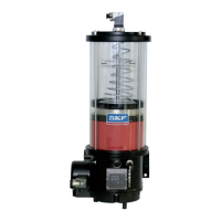
Pump units of the KFG, KFGS and KFGC series for rotary application
271-3034-EN
Explanation of order codes
Example: KFG 4 - 5 E O A X X B 0002 - 230VAC
Pump unit
Control unit
without marking=without control
S = with control and monitoring
1
)
C = in CAN bus design 24 V DC
2
)
Reservoir capacity
2 = 4 kg
3 = 6 kg 5 = 10 kg
4 = 8 kg 6 = 12 kg
Pump housing design
5 = version number
Type of fill level monitoring
X = without
E = 1 switching point, minimum, max. 230 V AC/DC
F = 2 switching points, minimum/maximum, max 42 V AC/DC
H = 3 switching points, minimum/minimum pre-warning/maximum, max. 30 V AC/DC
P = 2 switching points, minimum/minimum pre-warning, max. 230 V AC/DC
T = with current output KFG/KFGS 4 to 20 mA, KFGC 0.4 to 3.6 mA
Pressure regulating and relief valve
/ = without
M = with pressure regulating valve for multiple-line and progressive systems, 300 bar version, pivoted
N = with pressure regulating valve for multiple-line and progressive systems, customer-specific
3
)
O = with pressure relief valve for a single-line system with a pump element and integrated 200 bar pressure relief valve, 24 V DC
P = with customer-specific pressure relief valve (to be defined by customer)
Delivery rate of pump elements and their layout
X = without
A = 2.5 cm
3
/min. (1-groove)
B = 1.8 cm
3
/min. (2-groove)
C = 1.3 cm
3
/min. (3-groove)
D = 0.8 cm
3
/min. (4-groove)
E = 5.0 cm
3
/min. (no groove)
Layout of pump elements
Example of installed pump elements
Code installed pump elements
AAA = 1 and 2 and 3
AXA = 1 and 3
AXX = 1
Pump element position 1
Pump element position 2
Pump element position 3
Tube connection
/ = without
A = Ø 6 mm B = Ø 8 mm
C = Ø 10 mm
Version key
0002 = Basic design for rotary application
Motor key data
24VDC = Operating voltage 24 V DC , protection class IP 55
230VAC = Operating voltage 230 V AC (90 to 264 V AC), protection class IP 55
Example:
KFG pump unit (KFG) without internal control
unit, with lubricant reservoir size of 8 kg (4),
pump housing design (5) with switching point
fill level monitoring for minimum for external
output signal (E), with pressure relief valve for
a single-line system with a pump element and
integrated 200 bar safety valve (O), with
2.5 cm
3
/min. pump element mounted at
position 1 (AXX), with Ø 8 mm tube connection
(B), for rotary application (0002) with operating
voltage of 230 V AC and protection class IP55
(230VAC) gives the following order number:
KFG4 -5EOAXXB0002-230VAC
1) Notify us of the setting
times for the control unit.
2) System is designed
according to customer's
specifications.
3) On a design with a
pressure regulating valve,
its cracking pressure and
tube diameter are to be
specified (see pages 11
and 18).
Customer-specific requirements/accessories

 Loading...