Pump units of the KFG, KFGS and KFGC series for rotary application
6 1-3034-EN
Functional description of single-line
system with KFG pump unit
A general single-line system consists of the
following components: pump unit with pump
element, pressure relief valve with integrated
pressure regulating valve, main lubricant line
and single-line distributors. When the pump
motor is turned on, the piston pump delivers
lubricant from the reservoir to the lubricant
outlet. The pump element attached to the
outlet meters the lubricant and delivers it fur-
ther through the pressure relief valve at-
tached to the pump element on to the main
line. The lubricant flows through the main line
to the single-line distributors, where it is me-
tered and passed to the lubrication points.
This is performed during or after the pump
cycle time, depending on the type of feeders
used (prelubrication or relubrication feeders).
The
pressure relief valve switches after metering
is complete. After the main line has been re-
lieved, the single-line distributors are again
premetered and the pump unit is now pre-
pared for another lubrication cycle.
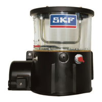
Single-line system with KFG pump unit
1 KFG unit
2 Main line
3 Pressure switch
4 Pressure relief valve
5 Single-line distributor
Example of single-line system with KFG pump unit
Functional description of single-line
system with KFG pump unit
The general functional description for single-
line systems with a KFG pump unit also ap-
plies for the design with KFGS pump control.
The control unit integrated into the pump
housing allows the following additional
conguration,monitoringandconnectivity
options:
Interval time and contact time can be •
adjusted independently, including on moni-
tored systems
Recording of remaining intervals and •
remaining lubrication times
Recording of fault notifications (diagnostics •
memory)
Data backup in case of voltage failure•
Non-volatile memory with PIN code •
protection
Connectivity for pressure switch•
Fill level monitoring, lubrication cycle and •
fault notification remain on display in case
the level falls below minimum
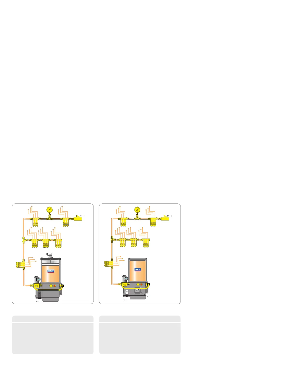
Example of single-line system with KFGS pump unit
Single-line system with KFGS pump unit
1 KFGS unit
2 Control/display
3 Main lubricant line
4 Pressure switch
5 Pressure relief valve
6 Single-line distributor
Functional description of single-line
system with KFGC (CAN bus) pump
unit
The general functional description for single-line
systems with a KFG pump unit also applies for
the design with CAN bus pump control.The
integrated LC-CAN 5000 control unit permits
the lubrication zone of a single-line distributor
system to be distributed into individual lubri-
cation zones for which individual parameters
(e.g. contact and interval times) can be set.
Up to four lubrication zones can be installed
in total. To distribute the lubricant, a corre-
sponding number of electric switch valves is
installed in the lubricant line leading from the
pump element. A valve is opened as soon as
the control unit starts a pump cycle period for
the corresponding lubrication segment. The
pump can only provide one lubrication seg-
ment with adequate lubrication, so it must be
ensured that only one valve is opened during
operation. This is handled by the control unit
in automatic and semiautomatic operation.
When CAN commands are used for control,
the valve opening must be ensured by select-
ing the appropriate contact and interval times
or by using appropriately programmed pro-
cesses in the external lubrication program
which switches the valves in a carefully coor-
dinated sequence so that only one lubrication
zone is activated at a time.
5
4
3
2
1
5
5
6
4
3
2
1
6
5
6

 Loading...