Pump units of the KFGS series for rotary application
16 1-3034-EN
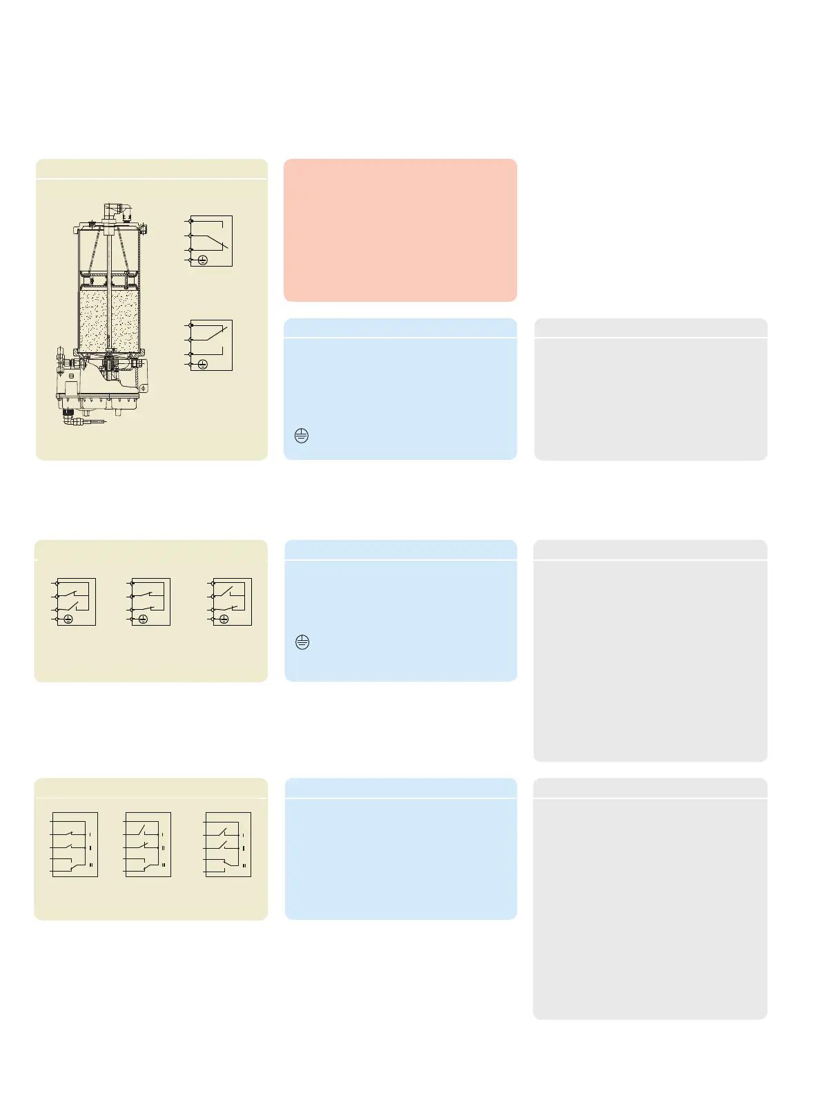
Fill level monitoring
Fill level switch E
Fill level switch F
Connector pin assignment, design E
Pin Description
1 = + Supply voltage
2 = Signal output
"above minimum"
3 = Signal output "minimum"
= PE Protective earth
Connector pin assignment, design F
Pin Description
1 = + Supply voltage
2 = Signal output "Maximum"
3 = Signal output "Minimum"
= PE Protective earth
Fill level switch E
Fill level switch F
Fill level switch H
Switch position at
minimum
Switch position at
maximum
1
6
4
3
+
5
1
6
4
3
+
5
Switch position at early
warning minimum
1
6
4
3
+
5
Fill level switch H
Connector pin assignment, design H
Pin Description
5 = + Supply voltage
3
2
1
Switch position at
minimum
Switch position
above minimum
3
2
1
Technical data, design E
Medium ................................NLGI Grade 2 greases
Fill level monitoring
Function ..............................Protective ground
Form of contact .................Changeover
Switching capacity, max. ....60 W/VA
Switching voltage, max. .....230 V DC/AC
Switched current, max. ....1 A
Connection diagram ..........EN 175301-803
plug Protection class .........IP 65
3
2
1
Switch position at
minimum
3
2
1
Switch position
between minimum
and maximum
Switch position at
maximum
3
2
1
Technical data, design F
Medium ......................... NLGI Grade 2 greases
Fill level monitoring
Function ....................... Reed contact
Form of contact .......... NO-contact/NC contact
Lubricant at "Early warning min." setting
4 kg Pump unit ...........1.0 kg
6 kg Pump unit ...........1.5 kg
8 kg Pump unit ...........2.0 kg
10 kg Pump unit ...........2.0 kg
12 kg Pump unit ...........2.0 kg
Switching capacity, max. 60 W/VA
Switching voltage, max. .. 230 V DC/AC
Switched current, max. . 1 A
Connection diagram ....... EN 175301-803 plug
Protection class ............... IP 65
Technical data, design H
Medium ............................NLGI Grade 2 greases
Fill level monitoring
Function Reed contact
Form of contact NO-contact/
NC contact/
changeover
Lubricant at "Early warning min." setting
4 kg Pump unit ...........1.0 kg
6 kg Pump unit ...........1.5 kg
8 kg Pump unit ...........2.0 kg
10 kg Pump unit ...........2.0 kg
12 kg Pump unit ...........2.0 kg
Switching capacity, max. . 60 W/VA
Switching voltage, max. 10-30 V DC/AC
Switched current, max. . 1 A
Connection diagram .......DIN 43 651 plug
Protection class ...............IP 65
Note
The customer evaluates the fill level switch
signal on fill level switch designs F, H, P and T.
However, on design E the evaluation is per-
formed by the pump's own IG5002-1 (dis-
play) control and monitoring unit.

 Loading...