Page 27
EN
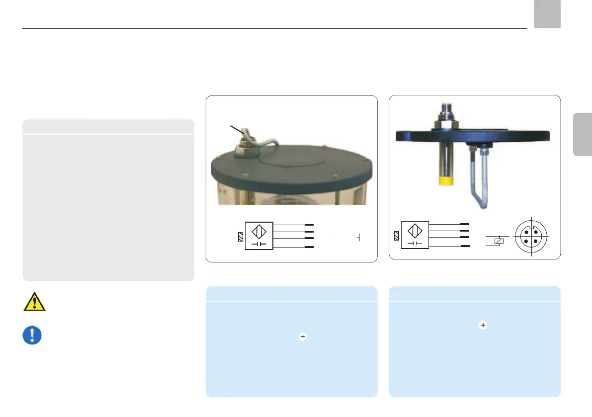
Cable connection - see table with cable
colors
BN
WH
BU
BK
1/+24 V DC
2/ not assigned
3/-OV
4/NO
4.5.2.4 Fill level monitoring
Technical data
Fill level ........Switch opens at min.
monitoring fill level, fault Function
notification and on wire breakage.
Operating voltage ....10 to 30 VDC
Continuous current ...
Internal power consumption 6 to 12 mA
Voltage drop ........
duration
EC Directives EN 6094752
Connection diagram .. M12x1 circular
connectors
Conducted interference per IEC 61000-4-6
(test level 3V). Radio interference is possible
between 2.4-2.6 MHz.
See assembly instructions on page 16
Warning!
-
Note
in addition to the two standard designs
must be connected according to the
provided customer drawing.
Cable assignment (on fill level switch)
Color Conductor Use
code coloring
BN Brown
Supply voltage
BU Blue O V (0 volts)
BK Black NO-contact
WH White Not assigned
Pin/cable assignment (pump unit)
Pin Color code Use
1 Brown
Supply voltage
2 White Not assigned
3 Blue O V (0 volts)
4 Black NO-contact
Cable socket
1
) per
DIN EN 60947/IEC 947
1) Cable socket - see Accessories, Chapter 14
KFG
Assembly instructions
BN
WH
BU
BK
1/+24 V DC
2/ not assigned
3/-OV
4/NO
1
2
4
3