Page 26
EN
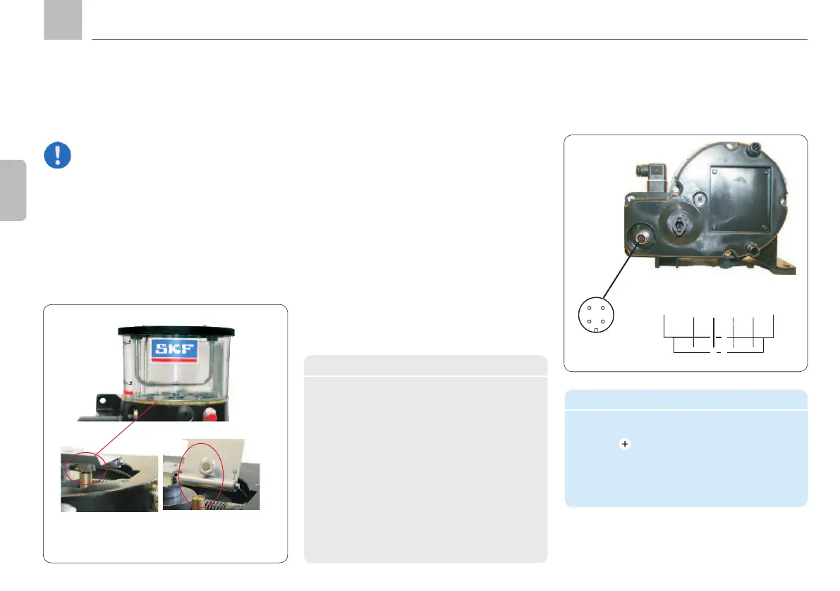
4.5.2.4 Fill level monitoring
4.5.2.3 External control
Type: W1 (max. 24 VDC)
for NLGI Grade 2 greases
Note
The external control units listed in
Chapter 17 are designed to control the
lubrication and interval times, as well as
to monitor the lubrication process.
Technical data
Fill level monitoring
Function ...... mechanical, via
floating reed
contact
Form of contact ..... NO-contact
Switching capacity, .. max.0.6 W
Switching voltage, ... max. 24 VDC
Switched current,.... max. 25 mA;
only ohm load
1
)
Plug-in connection ..DIN EN 60947/IEC 947
2
)
Connection diagram .M12x1 circular
connectors
1) No inductive load, no lamp load (signal lamp)
2) Cable socket - see Accessories, Chapter 17
W1 connector pin assignment (pump unit)
PIN Description
1 =
Supply voltage
2 = Signal output (W1)
3 = Not assigned
4 = Not assigned
Socket connection per
EN 60947/IEC 947
3 4
12
Functional description
The W1 fill level switch is designed as a rocker
switch and is integrated in the bottom of the
reservoir. A magnetic rocker mounted on the
agitator is turned downward by the grease re-
sistance when the reservoir is full. A pulse is
generated at each revolution of the agitator.
When the minimum fill level is reached, the
resistance the grease exerts on the rocker
subsides. The rocker turns back and the pulses
are interrupted.
Contact W1 open,
fault position
Contact W1 closed,
go position
KFG
Assembly instructions
1
2 3 4
+
Sig