Page 38
EN
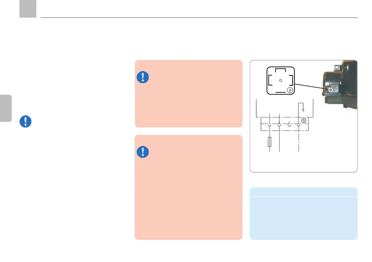
4.5.5 KFGS 90-264 VAC series with
integrated control unit
The electrical connection is established via a
plug-in connector per DIN EN 17530-803 for
the power supply (on the front of the unit) and
a 4-pin M12x1 plug-in connector per
EN 60947-5-2 (on the underside of the unit).
Unneeded conductor ends on the cable
set must be individually insulated and
secured so that no short to ground can
occur.
4.5.5.1 Power supply 90-264 VAC
X1 1 2 3
L1 N PE
90 - 264 V AC
47 - 440 Hz
C6A
F
)
1
Connector pin assignment for 90-264 VAC
PIN Code Description
1 L1 Main machine switch ON
2 N
3 Not assigned
PE Protective earth
1) = External control device "relay contact" "pump on"
Connector pin
assignment per
DIN EN 175 301-803
The "Timer operation with system
-
nectivity option (Chapter 6.5.5.1) is
also available in an advanced version
with a piston detector and fault signal.
A T connector with a special cable
adapter is required for this.
-
lustration of the connection, under
Accessories, Chapter 17.
order number of the M12x1
circular connector (mating part for
circular plug socket) required by the
customer in brochure No. 1-1730,
"Electric Plug-and-Socket Connectors."
KFGS
Assembly instructions