Page 39
EN
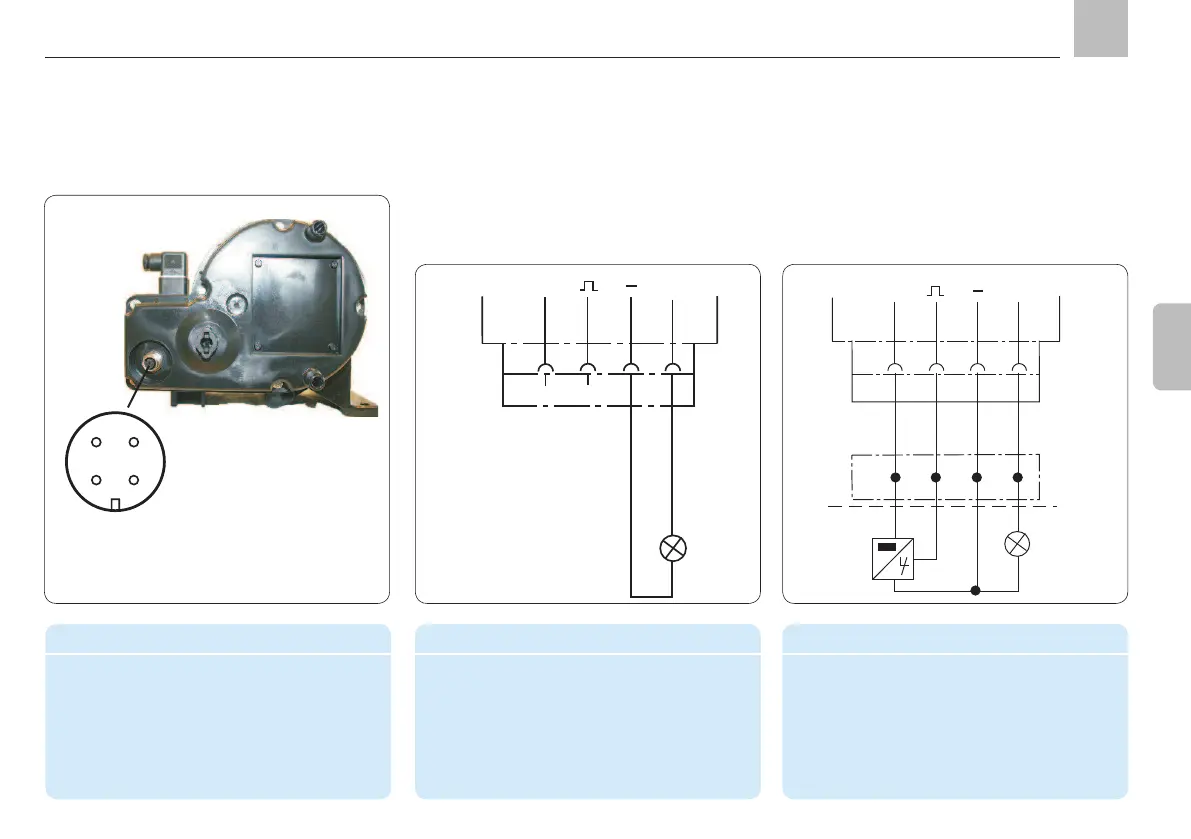
4.5.5.3 Connectivity for timer operation
without system monitoring
Programming: tPA, tCO, COP = OFF
24 VDC
+
X2
1
2
3
SL2
4
BU
BK
SL2
2,4W
4.5.5.4 Connectivity for timer operation with
Programming: tPA, tCO, COP = CS or PS
Socket pin assignment
PIN Color code Conductor coloring
1 BN Brown
2 WH White
3 BU Blue
4 BK Black
3
4
12
Socket connection per
EN60947-5-2
4.5.5.2 Connections for system monitoring
Connector pin assignment in timer operation
PIN Code Assignment
3 SL2 "Fault" indicator light ( - )
4 SL2 "Fault" indicator light ( + )
Connector pin assignment in timer operation
PIN Code Assignment
1 Voltage ( + )
2 CS/PS Cycle/pressure switch (signal)
3 SL2 "Fault" indicator light ( - )
4 SL2 "Fault" indicator light ( + )
24 VDC
+
X2
1
2
3
SL2
4
BN
WH
BU
BK
BN
BU
BK
X5
CS/PS
SL2
2,4W
1
2
3
KFGS
Assembly instructions