Page 33
EN
M L+ (Industrie)
1
BN
KFGS...
F
2 3 4 5 6 7
X1
RD-BK
BU
PK
VT-GN
MK
SL2
2,4 W
SL1
2,4 W
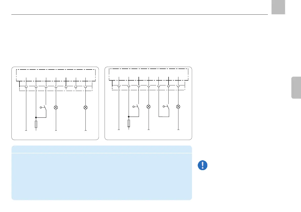
4.5.3.3 Connectivity for counter operation
without system monitoring
Connector pin assignment in counter operation
PIN Code Assignment
1 M - Supply voltage potential (0 V, GND)
2 L+ + Supply voltage potential "Main machine switch ON"
3 MK Machine contact
4 SL2 Indicator light "fault"
5 ZS Piston detector "+"
6 ZS Piston detector "signal"
7 SL1 Indicator light "pump ON"
4.5.3.4 Connectivity for counter operation
with system monitoring (progressive
centralized lubrication systems)
Programming: cPA, tCO, COP = OFF
M L+ (Industrie)
1
BN
KFGS...
F
2 3 4 5 6 7
X1
RD-BK
BU
PK
VT-GN
MK
SL2
2,4 W
SL1
2,4 W
BK
BK
ZS
+
Programming: cPA, tCO, COP = CS
One pulse is counted each time the
operating voltage is switched on when
the machine contact is closed in
counter operation.
Control using machine pulses
(Counter mode = load-dependent lubrication)
The duration of the interval time is determined
by a pulse generator that sends pulses to the
control unit based on how long the machine
has been running. The control unit counts the
pulses that are received and starts the pump
after the pre-set number of pulses.
value. Both the number of pulses that deter-
mine the interval time and the pump cycle
-
nected to the integrated pump control unit.
control level via indicator light SL2.
KFGS
Assembly instructions