Page 34
EN
4.5.3.5 Connectivity for timer operation
without system monitoring
Connector pin assignment in timer operation
PIN Code Assignment
1 M - Supply voltage potential (0 V, GND)
2 L+ + Supply voltage potential "Main machine switch ON"
4 SL2 Indicator light "fault"
5 PS Pressure switch " + "
6 PS Pressure switch "signal"
7 SL1 Indicator light "pump ON"
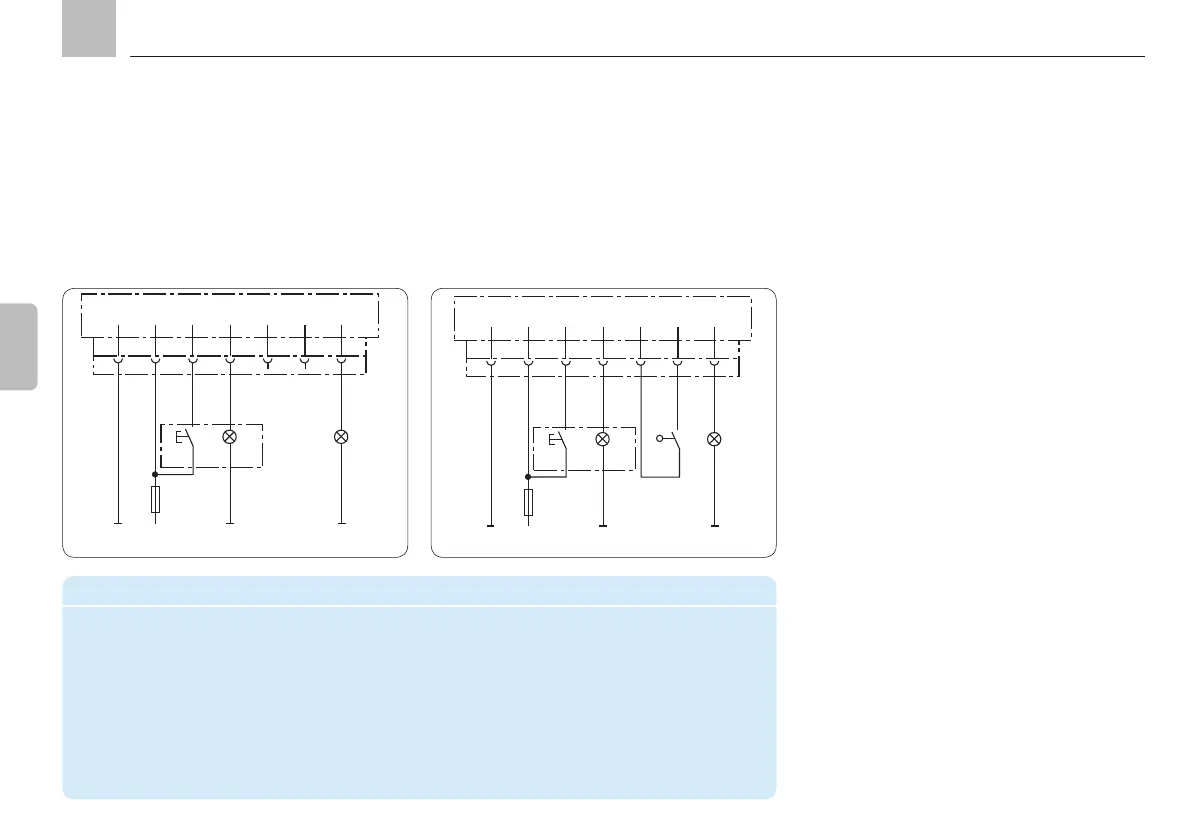
4.5.3.6 Connectivity for timer operation
with system monitoring
(single-line centralized lubrication system)
Programming: tPA, tCO, COP = OFF
1
BN
KFGS...
F
2 3 4 5 6 7
X1
RD-BK
BU
PK
VT-GN
DK
SL2
2,4 W
M L+ (Industrie)
SL1
2,4 W
1
BN
KFGS...
F
2 3 4 5 6 7
X1
RD-BK
BU
PK
VT-GN
DK
SL2
2,4 W
SL1
2,4 W
BK
BK
PS
+
M L+ (Industrie)
Programming: tPA, tCO, COP = PS
Timer mode
In timer mode, the interval time is determined
time value in hours.
value in minutes.
internally connected to the integrated pump
the process control level via indicator light SL2.
Settings for single-line lubrication
KFGS
Assembly instructions