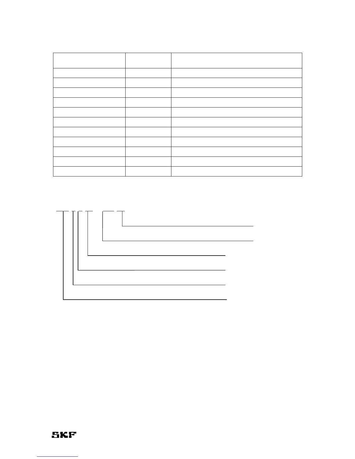
EasyManuals Logo

SKF Multilube User Manual

SKF Multilube
32 pages
To Next Page IconTo Next Page
To Previous Page IconTo Previous Page
Page #11 background imageLoading...
Page #11 background image
9
Symbols
MLP – A – B –C – D –E Abbreviation Description
MLP MLP Multilube-pump
A 4 Lubricant reservoir volume, 4 l
10 Lubricant reservoir volume, 10 l
B 1 Number of lines, 1-line system
2 Number of lines, 2-line system
C 12 Power input 12 V
24 Power input 24 V
D JB-103 User interface, JB-103
IF-103 User interface, IF-103
E PS Pressure control unit, built-in pressure switch
PSE Pressure control unit, built-in pressure sensor
Example:
MLP-4-2-24-JB103-PS
Power in
p
ut, 24 V
User interface, JB-103
Pressure control unit, built-in
p
ressure switch
Number of lines, 2-line s
y
stem
Lubricant reservoir volume, 4 l
MultiLube
p
um
p
Spare parts
See MLP-pumping unit spare parts (drawing no. 361304 in the next page).

Questions and Answers:

Question and Answer IconNeed help?

Do you have a question about the SKF Multilube and is the answer not in the manual?

SKF Multilube Specifications

General IconGeneral
BrandSKF
ModelMultilube
CategoryWater Pump
LanguageEnglish

Related product manuals