4
SKF Multilube pumping unit
General description
The pumping unit is designed for pumping lubricant into central lubrication system.
Design
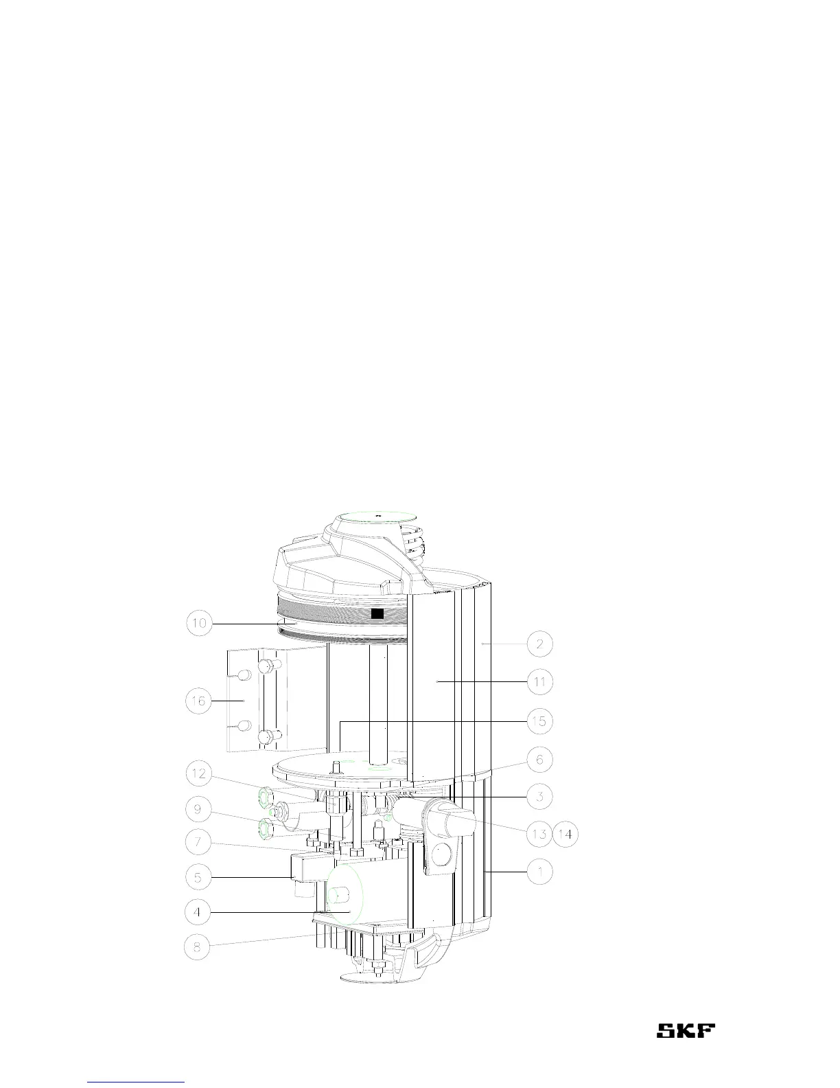
Pumping unit comprises of a body (pos. 1) and a lubricant reservoir (pos. 2).
The body comprises of a pump element (pos. 3), an electric motor (pos. 4), a line valve
(pos. 5), a pressure relief valve (pos. 6) and a heating element (pos. 7). Pumping unit is con-
trolled by a circuit board (pos. 8). (If external control is used, user interface and circuit board
are replaced with relays.) Pumping unit is equipped with a pressure sensor (pos. 9) for each
line which can be replaced with an external pressure control unit.
Lubricant reservoir is equipped with a follower piston (pos. 10), a level indicator (pos. 11)
and a low level switch (pos. 12). Filling connector (pos. 13) of the lubricant reservoir is
equipped with a filter (pos. 14) and a safety valve (pos. 15).
Pumping unit is equipped with a supporting block (pos. 16).