16
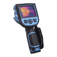
SKF TKTI 21 & 31
4. Using the Camera
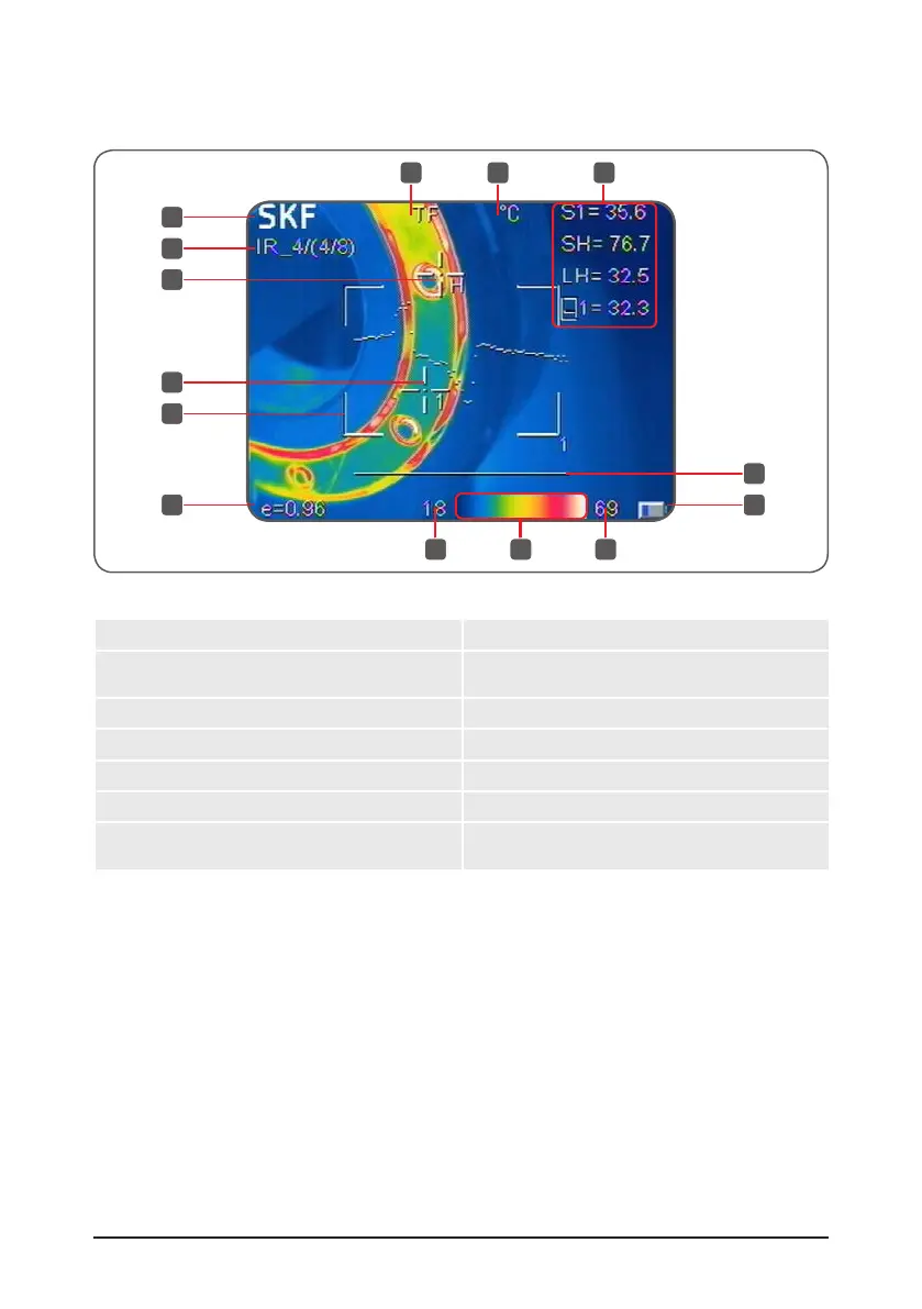
4.1 Screen elements
1
2
4
3
5
10
13 13
11
6
7 8
12
9
Figure 15 Screen elements
1. SKF on-screen logo 8. Temperature unit (°C, °F, K)
2. Operating status
(Saved image name, calibrating, L/S)
9.
Temperature readings, shows the temperature
of the spots, areas and lines displayed
3. Measurement spot with spot number 10. Global emissivity
4. Hot spot (H) and cold spot (C) 11. Battery status
5. Area 12. Colour palette
6. Line 13. Span and Level temperature limits
7. Memory card symbol, shown when the
Micro SD card is inserted
4.2 Menu functions
4.2.1 Measurement cursors
The measurement menu is used for adding or deleting spots, areas and lines.
• Press Menu button to activate the main menu.
• Select Measurement and press the Okay button.
1
2
4
3
5
10
13 13
11
6
7 8
12
9