Page 50 of 56
SKIPPER Electronics AS
Edition: 2021-09-16
ESN100 Operation and Installation Manual
Chapter: Appendix 1: Installation drawings
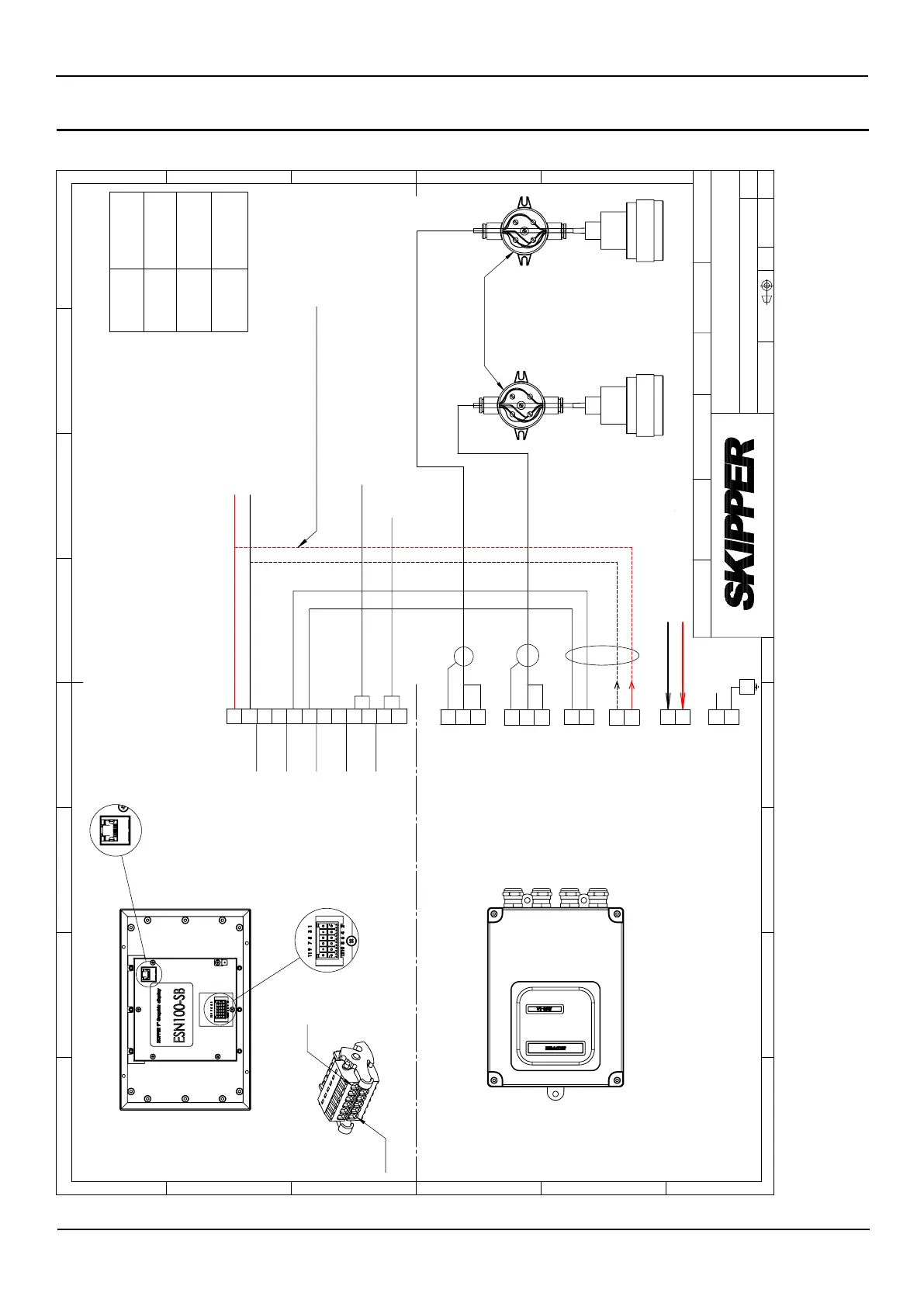
JB50E1-SA
Power to display (24VDC)
Power input (24VDC)
Transducer 1
Transducer 2
Pin 1
Pin 12
Cable shield not
to be grounded
J1
LAN (RJ45) for NMEA
communication and
remote control
Power input (24VDC)
NMEA IN 2
RS485 JB50
GND
(NMEA OUT 2)
NMEA OUT 1
NMEA IN 1
B+
A -
B+
A -
B+
A -
B+
A -
Transducer 2
Transducer 1
RS485 Display
J5
J4
J3
J2
24VDC
Shield to
connector
or Gland
Shield to
connector
or Gland
Shield
Gland
Output (DPT, ALARM)
Input (ZDA, ALARM, Position,
Speed, Dimming, Draft).
24VDC
Shield
Shield
A -
B +
-
+
-
+
* Display can be powered directly or
via JB50E1 unit.
+
-
Note 1
Cable spec
see Note 1
Cable spec
see Note 1
CN1
J1
Alarm relay
J6
Beeper
2
1
3
2
1
2
1
3
2
1
1
2
3
4
5
6
7
8
9
10
11
12
Length of
cable
Cable Area
0-100
1,5mm²
100-300
2,5mm²
>300
JB50E1 unit to
be mounted in
Bow
2
1
2
1
E
F
C
1
2
3
4
B
A
3
2
1
5
C
D
4
6
7
8
A
B
D
E
ISO2768m
Gen. tolerance
Eur. projection
Rev 01. Changed J3 Pin 1 to
B+
and pin 2 to A-. Renamed to
CD-2040-A ST 2020.08.27
Drwg. no.
Name
Edition date
Sheet
Revision
Scale
Designed by - date
Approved by - date
Electronics AS
Wiring Diagram ESN100
CD-2040
01
1 of 1
2020.08.27
2017.04.26 ST
2017.04.26 GT