Page 10
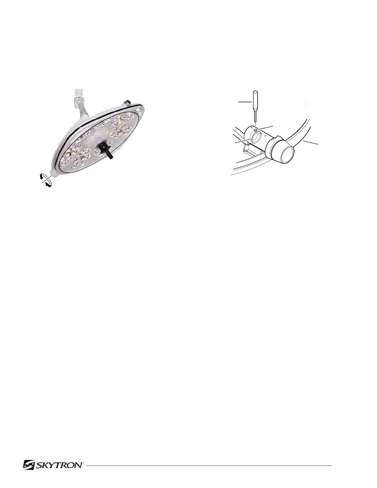
Figure 2-3. Lighthead Pitch Adjustment
d. Rotate the lighthead until a hole is visible and
insert a pin punch into the hole in the adjustment
nut.
e. With the nut held captive with the pin punch,
rotate the lighthead clockwise to increase the fric-
tion or counterclockwise to decrease the friction.
f. Remove pin punch and check adjustment.
Tighten set screws and replace top cover when
adjustment is complete.
Figure 2-2. Lighthead Pitch
b. The lighthead should move freely yet main-
tain its position without drifting. If an adjustment is
required, remove the top cover, refer to figure 2-3
and proceed as follows:
c. Rotate the lighthead until an allen set screw
is visible through the adjustment hole. Loosen the
set screw, rotate the lighthead 180° and loosen the
second set screw.
2-2. Lighthead Pitch Adjustment
a. Check the pitch axis tension of each lighthead
by moving it through its full range of motion. See
figure 2-2.
A
PIN PUNCH
HOLE
YOKE
SET
SCREW (2)

 Loading...


