Page 8
Operation
All parts of the camera system are suitable for use
within the patient area.
To ensure patient safety, do not touch any com-
ponent of the system and the patient simultane-
ously.
Turn main power switch on at the Wall Control.
Adjust the intensity control.
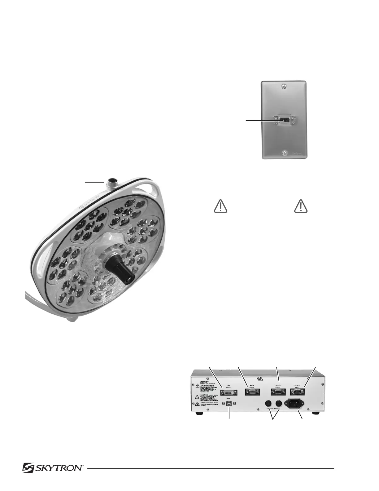
The focus of the bulbs within the lighthead can be
adjusted by rotating the sterilizable cover or the
side focus knob. See figure 6.
SIDE FOCUS
KNOB
Camera Control Unit Configuration
1. Attach the Cable from the connector on the
faceplate to the camera control unit (CCU). See
figure 7.
Figure 8. Camera Control Unit, back view
9 PIN
CONNECTOR
100-240V~,50/60Hz
100-240V~,50/60Hz
100-240V~
DVI
OUTPUT
RGB
OUTPUT
Y / Pb / Pr
OUTPUT
Y / Pb / Pr
INPUT
100-240V
~
INPUT
POWER CORD
CONNECTOR
2AMP
FUSES
USB
CONNECTOR
Figure 6.
To achieve optimal performance, install camera
control unit on a flat surface that is easily access-
able by the operator with a minimum clearance of
2” on sides. Do not block vents.
Figure 7. Camera Control Connector
Faceplate
WARNING
Outputs are for connection to video
components only.
2. Connect the video out cable (DVI, RGB, Com-
ponent) from the camera control unit to the monitor
or video imput.
3. Connect the power cord to the CCU and plug
into 100-240 VAC outlet. See figure 8. This power
cord is considered the main disconnect device and
should remain accessible at all times.
4. USB connector is provided for connection to
external control system.

 Loading...


